11 - VBOX Test Suite Map
The map area is an area that shows a positional trace from either the saved data contained within a file or real time live data. A location cursor displays the location of the vehicle. To provide the greatest accuracy, the map uses the EGM 96 Geoid of Earth.
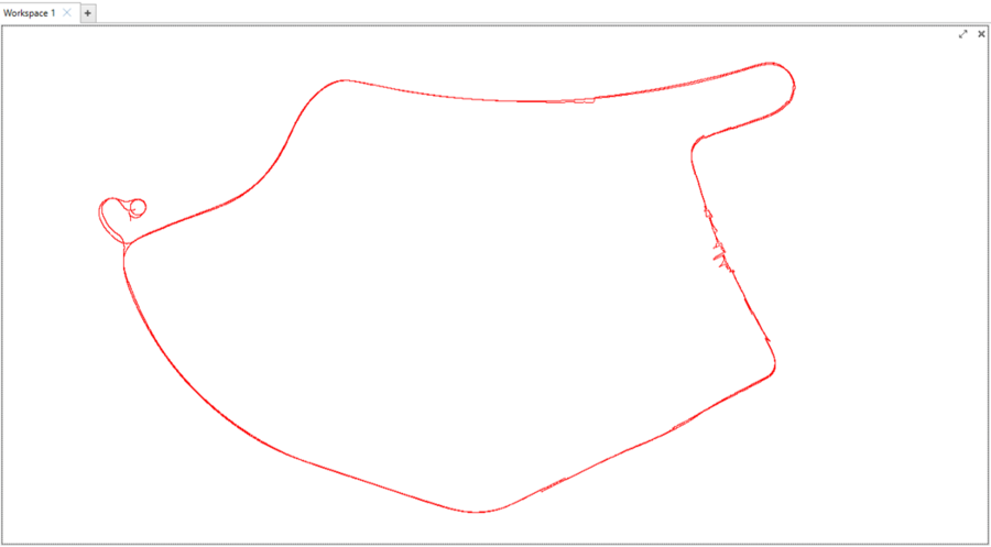
In online mode, the map will be centred on the vehicle and will display real-time data.
The map tab is where the user can access all the functionality of the map. This tab will be displayed when the user clicks anywhere on the map area and will automatically be selected.
Ribbon Bar
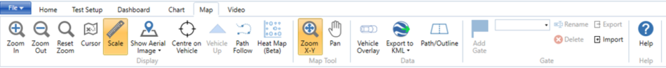
Note: Ribbon bar icons may move/ resize dependent on the Software window size.
Display
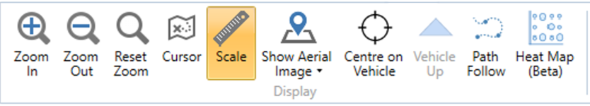
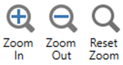
Zoom in
The 'Zoom In' button zooms in on the map, centred around the cursor position.
Zoom out
The 'Zoom out' button zooms out on the map, centred around the cursor position.
Reset Zoom
The 'Reset Zoom' button returns the map to full view.
Cursor
The 'Cursor' button allows you to change how the location cursor is viewed within the map area. Clicking on this button brings up a pop up window that allows the user to change the type of cursor from the default cross, to a circle, triangle or square. The size, thickness and colour of the cursor can also be configured.
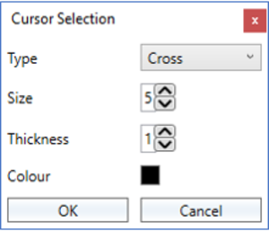
Selecting ‘OK’ will close the window and apply the new cursor settings, selecting ‘Cancel’ will close the window without saving the changes.
Scale
The 'Scale' button will add a scale to the map. Selecting this button again will remove the scale from the map window.
Show Aerial Image/Road Map
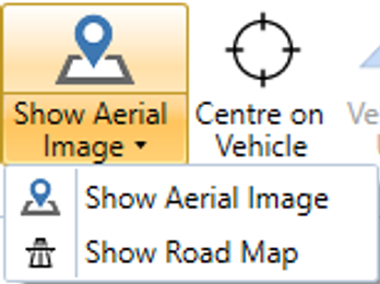
Selecting 'Show Aerial Image/Road Map' dropdown menu will overlay either an aerial image or road map from Bing Maps onto the map area. Selecting the icon will toggle that image/map on or off, the icon and dropdown menu title will change dependent on which option is selected.
|
|
|
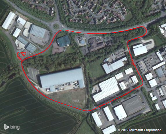 Aerial image
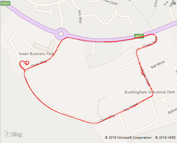
Note: An active internet connection is required to use this feature.
Centre on Vehicle
The 'Centre on Vehicle' button will centre the vehicle within the map in whichever part of the data is selected. Selecting this button again will remove this centring functionality.
Vehicle Up
The 'Vehicle Up' button changes the map orientation so that the Vehicle is always pointing up the map, instead of the default ‘North up’ behaviour.
Note: In 'Online' mode this is set as default.
Path Follow
The 'Path Follow' button changes the map behavior so that the user can easily follow a predefined path. This mode predicts where the vehicle will be in x seconds based on the vehicle’s current speed and heading.
Turning this mode on brings up a pop up window that allows the user to configure how the mode should operate.
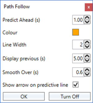
Selecting ‘OK’ will close the window and apply the Path Follow settings, selecting ‘Turn Off’ will close the window without applying the mode or saving changes.
Predict Ahead (s)
The predict ahead option changes the length of time for which the software will predict the path.
Colour
Changes the colour of the prediction line.
Line Width
Changes the width of the prediction line.
Display previous (s)
Selecting this option will show the previous path of the vehicle. The length of this trace can be changed by modifying the seconds value.
Smooth Over (s)
Changes the time at which the vehicle path will be smoothed. A higher value will yield a more stable value but will be less responsive to dynamic change.
Map Tool
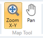
Zoom X-Y
The 'Zoom X-Y' button defines how the left click and drag action is performed. When selected, Left clicking and dragging the cursor to the right will perform a ‘box zoom’ of that area. To return to the full view, simply click and drag the cursor to the left.
Pan
The 'Pan' button defines how the left click and drag action is performed. When selected, Left clicking and dragging the cursor will pan the map accordingly.
Data
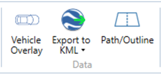
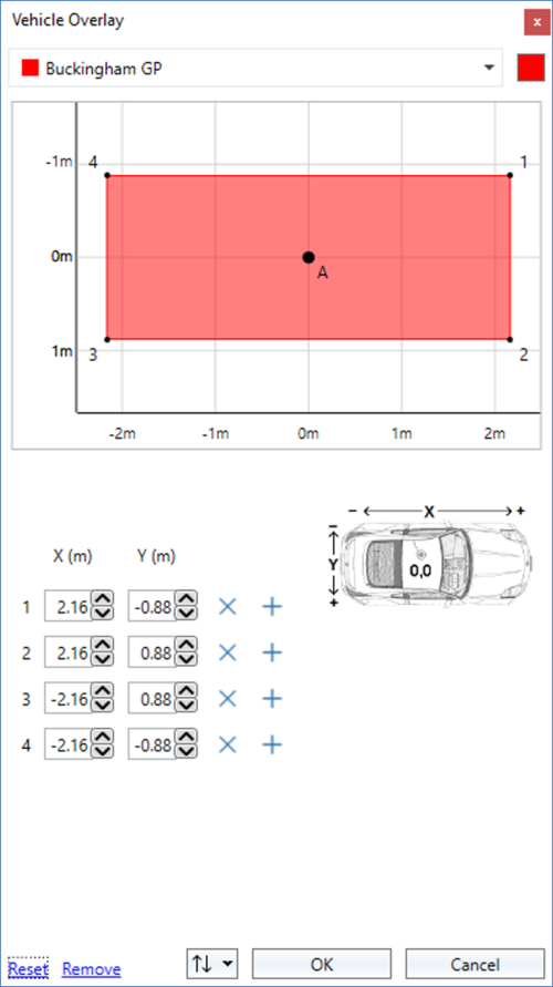
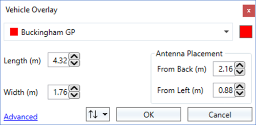
Vehicle Overlay
|
The ‘Vehicle Overlay’ button opens up a settings window where you can create a shape to represent the dimensions of the vehicle within the map area. If you enter the vehicle size and antenna placement offsets, the software will create a 4-sided object representing the vehicle and will overlay this on the cursor within the map. Selecting ‘OK’ will close the window and apply the vehicle shape, selecting ‘Cancel’ will close the window without applying the shape or saving changes. |
|
|
The colour of the represented vehicle can be changed by clicking on the existing colour on the top right of the window.
Selecting ‘Reset’ will revert the window back to the previous standard one and will disregard the changes. Selecting ‘Remove’ will remove the vehicle dimension object from the map area. Selecting ‘OK’ will close the window and apply the vehicle shape, selecting ‘Cancel’ will close the window without applying the shape or saving changes.
The vehicle overlay can be exported as a .veh file for reuse at a later date, or imported from a previously created overlay by selecting the up/down arrow dropdown menu
The direction of the represented vehicle is determined by which channels are being calculated. The channel order used to calculate the direction of the vehicle is as follows:
|
 |
 .
.Export to KML
The 'Export to KML' allows the user to export the positional trace to the .kml format that can be understood by programs such as Google Earth.
Path/Outline
Allows the user to load a reference path (.vbo, .dbn, .vbc or .cir file) that can be used with the path follow mode, or as a visual reference. On the load of a path, the software will automatically calculate the perpendicular distance from the lane to the vehicle as well as the distance from the lane to the predicted point. These channels can be displayed on the dashboard and as well as a graphical trace on the chart.
Gate
The Gate area will mirror the gate options available in each test. You can find more information on the individual Test Page. If you have not chosen a test, the Gate area will default to the following:
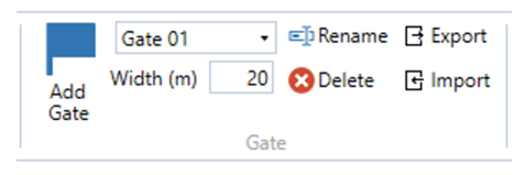
Add Gate (Space)
Clicking the Add Gate button will add a virtual gate to the chart and map at the point of the cursor. You can also add a gate at your current location by pressing the space button on your keyboard. The gate is indicated by green lines. The currently selected gate will be indicated by a blue line.
When you have added a gate, you can specify the gate width. The default gate width is 20 m.
Note: If you change the gate width, the last used gate width will be used as the default width for the next gate.
You can now use the gates as start or end conditions.
Note: Opening a plugin (either as a new tab or overwriting an existing one) will clear all set gates. If you do this you must, therefore, redefine the gates before you amend the test configuration to set start/end conditions.
|
IMPORTANT |
Rename
Click on this button to rename the currently selected gate line.
Delete
Click on this button to delete the currently selected gate line.
Export
Click on this button to export the created gate(s) as a .spl file that can be reused at a later date and can be used with another VBOX product.
Import
Click on this button to import a previously saved or provided .spl file. When this is imported, the gates will be added in the order that they were saved in the .spl file.
Help
Pressing this 'Help' button will automatically open an internet browsing window and load the relevant section of the Racelogic Support Centre. This page will only be displayed if there is a valid internet connection.
Map Functionality
Navigating around the map
The user is presented with 3 ways to zoom the graph in and out, the first being the button in the Chart tab.
By pressing the ‘Zoom In’ or ‘Zoom Out’ button, the graph will zoom in/out by 5%. The user can reset the graph to the default zoom level by pressing the ‘Reset Zoom’ button.
These buttons will also briefly appear next to the map cursor any time the user clicks/touches anywhere on the map trace. The user can then use these buttons as above.
The final way to zoom is by using the mouse. The user can either double click anywhere in the map window to slowly increment the zoom level, use the scroll wheel to zoom either in or out or left click and drag to perform a ‘box zoom’ (providing the ‘Zoom X-Y’ button has been selected). If you have used a box zoom whilst the 'Centre on Vehicle' option is selected, the map will zoom in to the box location and then once the cursor is moved, move back to the centred vehicle.
Panning
When zoomed in, it is possible to right click anywhere within the map window and move the window around.
The same action can be performed with the left click, providing that the ‘Pan’ button has been selected on the ribbon.
Selecting the 'Left/Right' keyboard keys will move the cursor left or right.
Save/copy image
Right clicking within the Map area allows the user to either copy the view currently seen within the map window as an image to the computer clipboard, or save locally as a .png, .bmp, .gif, .jpg or .tif file.