03 - CAN Gateway Setup CAN Conversion
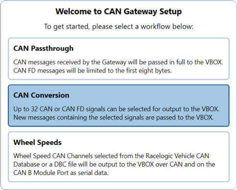
Selecting the 'CAN Conversion' option on startup allows you to configure CAN Gateway to convert up to 32 CAN or CAN-FD signals received from a vehicle CAN Bus to CAN signals used by a VBOX.
The process involves loading a CAN/CAN-FD .dbc file(s) in to the software, selecting any required signals, selecting the desired the CAN Configuration settings for the vehicle and VBOX CAN ports and then generating a configuration file for use by CAN Gateway and a .dbc CAN file for use by the data logger.
Overview
Signal Sources
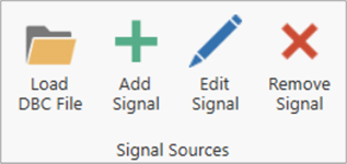
Load a DBC File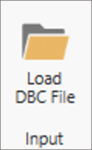
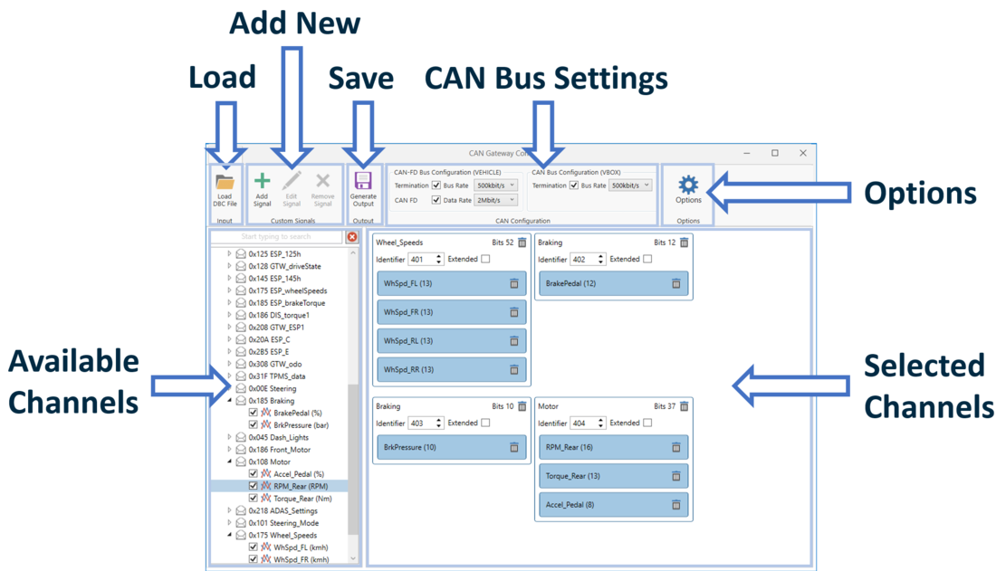
To load a CAN or CAN-FD .dbc file, press the 'Load DBC File' button at the top of the window. You can then browse your computer to find the local .dbc file and press 'Open' to open the file within the software. Multiple files can be loaded in to the software.
All available signals are displayed on the left hand side of the screen. To select a signal, navigate through any dropdown menus if applicable and tick the box next to the left of the signal name. A maximum of 32 CAN or CAN-FD signals can be selected. A search bar is also available at the top of the listed signals to allow you to search for a CAN signal.
Any selected signals appear within in the main area of the software within an output message. The number of bits related to each signal is stated after the signal name. The output message header text contains the name and number of used bits. You can edit the identifier number and also choose to use the extended identifier. The signals are added to the first available compatible output message. Signals in compatible messages are sorted by signal length, packing the smallest signals into any gaps. Signals can only be added to a new output message or an output message that already contains signals from the same source message.
Signals can be removed by unticking the signal name on the left or by selecting the Trash Icon  next to a signal.
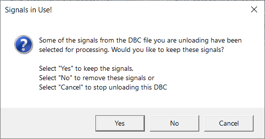
To remove the loaded .dbc file, right click on the file name on the left hand side of the screen and then select 'Unload'. If some of the signals from the .dbc have been selected for processing, a warning popup will be shown. If you would like to keep the signals, select 'Yes', if you would like to remove the signals, select 'No', if you would like to cancel the .dbc file removal, select 'Cancel'.
Add a Signal
|
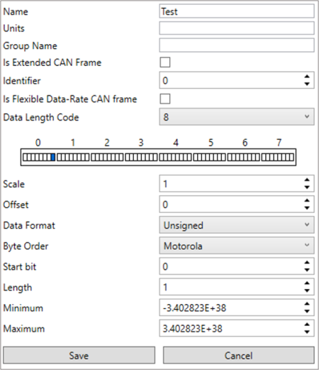
As well as loading pre-defined CAN/CAN-FD database files, there is the ability to manually enter details of individual CAN signals. This requires the user to have an in depth knowledge of the CAN bus system they are connected to.
Once the details of the signal setup have been entered, press Save to confirm the settings. The signal will then be automatically selected and appear within an output message on the right hand side of the screen. |
 |
Edit/Remove Signal
To edit a custom signal, select it from the Available Signals and click on Edit Signal. Alternatively, to delete a signal, select the signal and press Remove Signal.
CAN Configuration
The CAN Bus Settings area enables you to define the vehicle and VBOX CAN/CAN-FD baud rates, data rate and allows you to select termination.
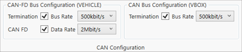
CAN Bus Configuration (VEHICLE)
Define the vehicle CAN- bus baud rate (selectable as 125, 250, 500 kbit/s (default) or 1 Mbit/s). Click here for details on how to physically measure CAN baud rate.
If you are using CAN-FD signals, ensure that the CAN FD box is checked. Once selected, choose the desired data rate (selectable as 500 kbit/s, 1, 2 (default), 3 or 4 Mbit/s). Once the CAN FD box is checked, the only selectable vehicle CAN bus and VBOX CAN bus baud rates are 500 kbit/s or 1 Mbit/s.
CAN Bus Configuration (VBOX)
Define the VBOX CAN bus baud rate (selectable as 125, 250, 500 kbit/s (default) or 1 Mbit/s).
Termination
Within the settings area, it is also possible to select termination in relation to the vehicle and VBOX CAN bus (on by default).
When connecting to Racelogic modules and other CAN data-loggers and sensors, additional CAN termination may be needed depending on the specific setup. Click here for more information on CAN termination.
Save Configuration
When you have selected the required settings and CAN/CAN-FD signals you would like to output as CAN messages, you can save the GWCONFIG.INI configuration file to CAN Gateway, and save the generated GW-CONFIG.DBC file locally on the PC so that you can load it onto the logging device.
Connect the CAN Gateway to a PC via USB. Use the supplied RLCAB117 cable and connect to the USB connector on the front panel of the unit.
Note: If you are unable to connect the CAN Gateway to a PC, you can save the configuration file to the PC and transfer the file over later.
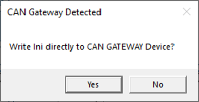
Click on the 'Save Config' button at the top of the window. The software will open a navigation window where you can browse your computer to select a folder location you want to save both files. A subfolder will be created in this folder that will automatically be time and date-stamped. If the CAN Gateway is connected and detected, the software will ask you if you would also like to save the GWCONFIG.INI configuration file directly to the CAN Gateway. This will save you from transferring it separately.
You can now load the newly generated .dbc file onto the VBOX logging device via the relevant configuration software and make sure that it is ready for use with the CAN Gateway.
For example, if you are using a VBOX 3i:
- Connect VBOX 3i to a computer via either Bluetooth, an RLCAB001 cable from the 'SER' input and the computer's serial port (USB-serial adapter may be required), or via an RLCAB066-2 cable to one of the computer's USB ports.
- Open VBOX Setup Software and connect to the unit.
- Navigate to the 'Channels' menu.
- Click on the 'Internal CAN Input' tab and then select a channel.
- Choose to 'Load' a User CAN Database file, browse your computer to find the previously saved .dbc file and press 'Open' to open the file.
- Select the desired channel and press 'OK' to load. Repeat as necessary.
- Select 'Write to unit' to save the configuration to the VBOX 3i.