02 - MIM Inputs / Outputs

Thermocouple inputs
The MIM01 has 2 K-type thermocouple inputs, each input is capable of measuring temperatures from 0 - 1000°C.
Each socket is the standard thermocouple socket format; the Green colour on a thermocouple plug indicates a K-type
thermocouple, +ve (green wire) on the thin spade terminal.
See the Specification table for full thermocouple specifications
Status lights:
- Green light indicates a functioning thermocouple is connected.
- Red light indicates no thermocouple connected or a problem with the thermocouple.
.png?revision=1)
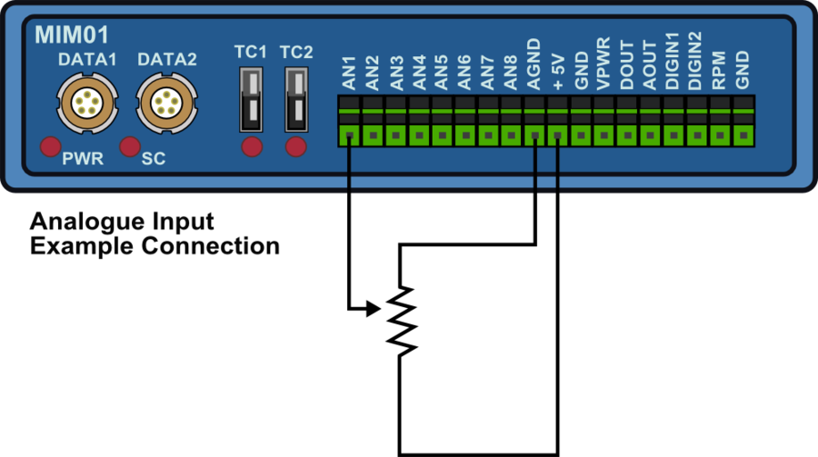
Analogue Inputs
All of the analogue inputs are non-opto isolated 14 bit 0 - 14 V inputs, and they are all non-differential inputs that share the same ground.
An example of how to connect an isolated individual potentiometer is shown below.
Connecting to a potentiometer already installed on a car, such as a throttle potentiometer, would only require the output signal from the pot and the earth to be connected to the MIM01 as the pot gets its power from the car.
Digital Inputs
The digital inputs are optimised to suit certain applications.
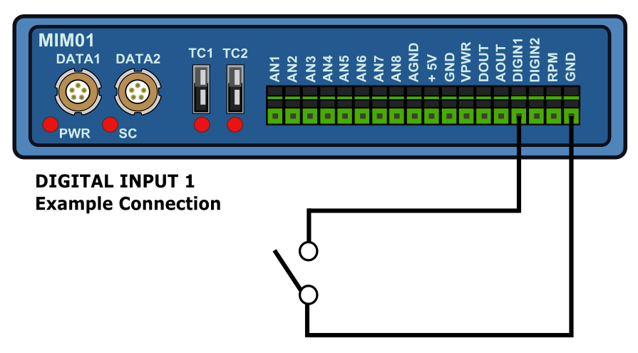
- Digital Input channel 1
Optimised for event marking due to its internal 100 Kohm pull up resistor, with a simple switch that connects the input pin to ground. The low state is below 4 V so it can also be used as a TTL pulse input, such as fuel flow sensor inputs.
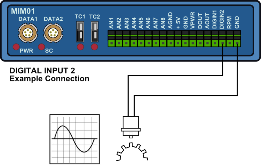
- Digital Input channel 2
Optimised for a zero crossing AC input signal such as a Wheel speed signal or engine crankcase signal.
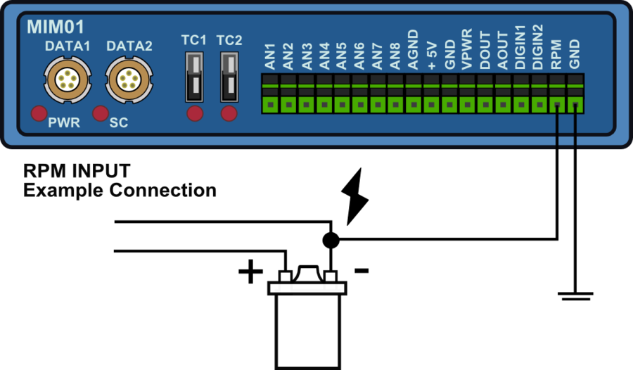
- RPM input, Digital input 3
Optimised for low-tension ignition coil signals.
See the Specification table for full digital input specifications
The Name and Units for each Digital input channel can be configured. There are also other modes and options configurable depending on the Digital Input channel.
| Digital Input 1 | Digital Input 2 | Digital Input 3 |
|---|---|---|
| Name | Name | Name |
| Units | Units | Units |
| Mode - event marker/frequency/pulse | Mode - frequency/pulse | Pulse/Rev |
| Scale | Scale | |
| Edge – (only in frequency mode) | Edge – (only in frequency mode) | |
| Active – (only in event marker mode) |
Mode
Changes the input mode of the digital channel.
Edge
This contains two options that determine whether the frequency is measured from the RISING or FALLING edge of the signal.
Active
High or Low, this determines whether the input trigger state is logged in an inverted or non-inverted state, see the table below.
| Logged Trigger State | ||
|---|---|---|
| Input State | Active - Low | Active - High |
| Low | High | Low |
| High | Low | High |
Digital input connection examples
Example 1 below shows an example of an event marker switch connection to the Digital input 1, which is hardware optimised for event marker use.
Example 2 shows a typical connection to a wheel speed or crankcase sensor.
Example 3 shows a typical connection to the ‘low tension side of an HT coil for RPM pickup.
Analogue and Digital Outputs
The Digital and Analogue outputs both output velocity when connected to a VBOX Mini. The pulses/metre of the digital output and the max velocity (at 5 V) for the analogue output is set in the Input Module Menu on the VBOX Mini.
- Press the MENU button to enter the Input Module Menu.
- Highlight the Setup Outputs option by using the ▲▼buttons then press OK to enter the Setup Outputs option.
- Use the ▲▼buttons to scroll between the Analogue Output MAX Speed and Digital output Pulses/Metre options, then press OK to edit the value an individual option.
- Press the ▲▼buttons to adjust the value and then press OK to set the value.