Setting up a Weather Station
Overview
For Pass-by Noise Testing, weather data is important in particular, the criteria for a successful test pass requires wind speed and temperature to be within a certain threshold. To automate the test checking as well as for logging purposes, a Mini Input Module, Road side Telemetry radio and Davis Vantage Pro 2 Station (shown below) with Serial Weatherlink data logger allows wind speed, direction, air temperature, humidity and barometric pressure to be sent to the VBOX 3i data logger in the vehicle.
Equipment
- 1 x RLACS112L; 5 Ah Li Ion battery pack
- 1 x RLRTM24MBC; Road side Telemetry Radio
- 1 x RLCAB005 radio modem Cable to Mini Input Module
- 1 x RLVBMIM01; Mini Input Module
- 1 x RLCAB143; B&K 2250 SLM DC output Cable to Mini Input Module
- 1 x Davis Vantage Pro 2 Station with Serial Weatherlink data logger
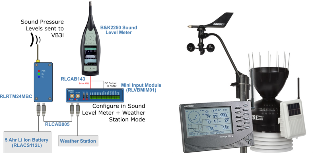
Weather Station setup for Pass-by Noise Testing (Left) and Davis Vantage Pro 2 Weather Station (Right)
Weather Station Setup
The Integrated Sensor Suite (ISS) can send data either wired or wirelessly to the Vantage Pro 2 console depending on the version you have. Check that the Serial Weatherlink Logger is installed in the console and use a RLCAB032 cable to connect the D9 connector of the Weather Link Logger and the Mini Input Module Data 2 port.
- Assemble the ISS as per the manual.
- Power the console if it does not already have power. Refer to the Vantage Pro 2 Console User Manual.
- If the console is not in Setup Mode, press and hold ‘DONE’ then press the down arrow. The message ‘RECEIVING FROM... and STATION NO.’ followed by the Transmitter IDs that the console detects displays on the console screen.
- Look for the ISS Transmitter ID. The number 1 displays unless the Transmitter ID has been changed. If the ISS Transmitter ID is displayed, the ISS is detected.
- Press and hold ‘DONE’ to view ISS data once the ISS Transmitter ID displays.
- If the console is in Setup Mode, press and hold ‘DONE’ until the Current Weather screen displays. A flashing 'X' in the lower right hand corner indicates that the console is receiving data packets. This may take a few minutes.
- Sensor readings from the ISS should display on the screen.
- Near the centre of the screen, look for the outside temperature (TEMP OUT).
- Spin the wind cups to check wind speed, pressing ‘WIND’ if necessary to alternate between speed and direction in the compass rose.
- Turn the wind vane, and allow 5 seconds for the wind direction display to stabilise before moving it again.
- Approximately one minute after power-up, the outside relative humidity (HUM OUT) reading should be displayed on the console.
Firmware Upgrade
Load the latest firmware into the Mini Input Module and VBOX 3i from the VBOX Automotive website.
Instructions on how to do this can be found at MIM Firmware Upgrade and VB3i Firmware Upgrade.
Mini Input Module (MIM01) Setup
- Install the latest version of VBOX Setup which can be downloaded here.
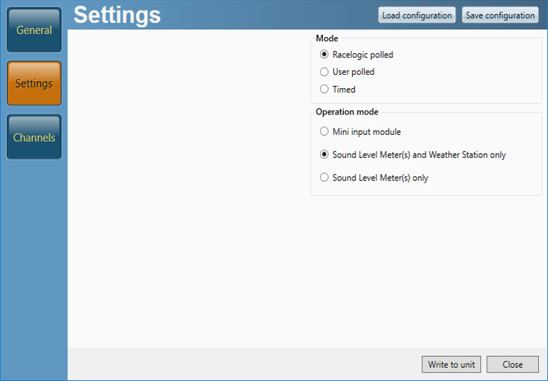
- Go to ‘Settings’ and toggle the Operation mode ‘Sound Level Meter(s) and Weather Station only’ as shown below and click on ‘Write to unit'.
When in this mode, please note that the Mini Input Module Data 2 port can only be used for receiving weather station data.
VBOX 3i Setup
- When the laptop has made a connection to the VBOX 3i using VBOX Setup. Click on ‘Channels’, then ‘Internal Pass-By Noise’ and the first tab as shown below.
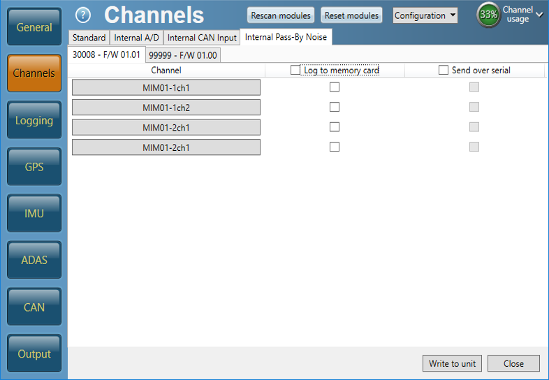
- If connecting Sound Level Meters to this Mini Input Module only, click on ‘MIM01-1ch1’, the channel name and units can be changed. For B&K 2250 SLM units, set the scaling to ‘50’ and click ‘OK’. Repeat again for ‘MIM01-2ch2’.
.png?revision=1)
- Check ’Log to memory card’ and ‘Send over serial’ boxes as shown below.

- Within the same menu, select the second tab, check ’Log to memory card’ and ‘Send over serial’ boxes as shown below.
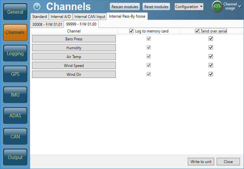
- Click the ‘Write to unit’ button.
- Close VBOX Setup. Both RX/TX LEDs should be both flashing on the radios, this demonstrates that the Road Side equipment and the VBOX 3i are communicating correctly with each other.
Detailed instructions on how to use the Pass-By Noise Software Plug-ins are available within in the VBOX Test Suite R41 and R51 user manual pages.