12 - TC Tips and Tricks
Power Supply for the RLTC ECU
Recommend connecting to the same power supply as the vehicle’s ECU since this will not go to ground when turning the engine over.
Launch Control
There are 2 launch control rev limits to set – Wet Launch and Dry Launch. Dry Launch should be set at the RPM where peak torque occurs. Generally Wet Launch should be set at 1000rpm below peak torque.
*Remember launch control will only work on a vehicle with a manual transmission.
Using the terminal to configure parameters
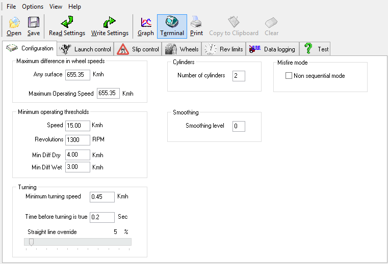
The setup software also features a terminal that allows the user to view information in real time and configure various parameters. To access this select terminal in the setup software.
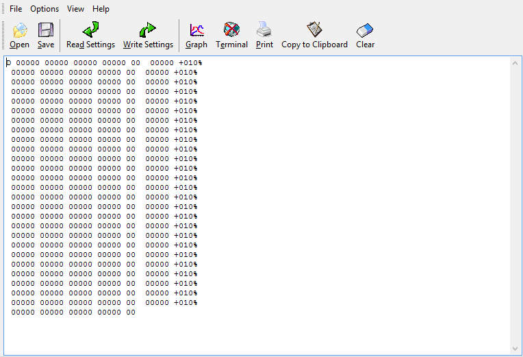
To view real-time wheel speeds, cut level, RPM and adjuster slip setting. Type D to start the terminal updating as below (and D again to stop the terminal updating).
To view other information select Read Settings whilst viewing the terminal screen. You will then be presented with the menu below:
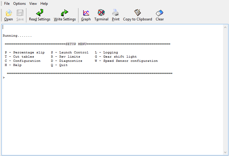
Follow the prompts within the terminal to configure settings.
For example:
Press ‘C’ to configure the RPM at which the LED is activated. For 7000 RPM type ‘07000’.
Exit Terminal – settings will now have taken affect.
(Note when this value is changed from 65535, the Diagnostic LED will no longer flash to indicate RPM/WSS signals are present, as described in page 22 of the manual)
Digital Adjuster internal board references
If a Digital Adjuster is taken apart for some reason, references for the Blue and Red wires appear wrong. However, the Digital Adjuster is wired correctly so leave it as it is.
Rev Limiter
By inverting the clutch switch on the rev limits tab in the software, this effectively gives you a secondary rev limit just in case the factory one fails, or if you simply want to lower the rev limit of your engine, like ‘Valet Mode’ This is useful if a 3rd party is required to drive your pride and joy.
Batch Fire Injectors
Batch fire is where one injector signal output from the ECU controls two injectors in parallel. For example, 4 signal outputs on a V8 instead of 8.
If this is the case, then you need to interface with each injector individually. Therefore connect after the signal splits off to each injector.
RLTC on a Mazda RX7
Racelogic Traction Control is wired up exactly the same on a rotary engine as it is on a piston engine. The injectors are wired up as normal, however you must make sure that non sequential mode is ticked in the software.
Please note, even though there are only 2 rotors there are actually 4 injectors: Primary (normal) and secondary (full throttle or full boost on the FD3S)
LED cuts indicator
Basically the best way to do this would be to use an LED, connect the Anode using a 66 Ohm resistor in series with the LED connected to Pin 15 of Connector A, then connect the Cathode to pin 4 of Connector B. That way there will be a drop of 3V across the LED when pin 4 goes to ground during injector cuts but no drop at any other times.
ABS Light on
- Check you have connected to the same side of all 4 sensors.
- The RLTC system might be ‘loading’ the ABS module a bit too much. Try adding in-line resistors between the ABS signal wires the RLTC ABS wheel speed interface wires. 10kΩ – 20KΩ should be fine.
RLTC on a Dodge Viper- Check Engine Light on
The OEM Dodge Viper ECU requires injector ring back signals which the RLTC ECU cannot replicate.
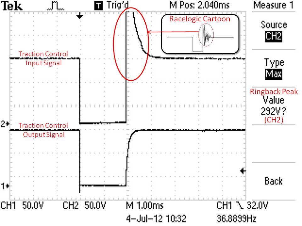
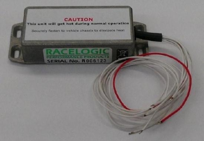
We can supply a coils module which will replicate these signals – Part Number is TC8COIL-3.
.jpg?revision=1)
Cars with only 3 wheel speed sensors
Some cars have a single sensor for the rear wheel speed that is mounted on the differential e.g. Nissan 200SX and some older Mercedes Benz. This means that the TC system cannot calibrate itself automatically. This can only be done via a laptop using the software.
Procedure for configuring cars with 3 wheel speed sensors
1. Locate the three sensor wires (See 1.5.3 Connecting Traction Control ABS Wires).
2. Identify which signal wire is from the rear sensor.
This can be done using any of the following methods
- Wiring Diagrams - If you have a wiring diagram of the vehicle, trace each of the sensor wires to the ABS unit, the wiring diagram will normally indicate colour codes. If you have books such as the “Autodata - Anti Lock Braking Systems” series these can help in identifying the wiring. (Contact Racelogic if you do not have one).
- Multimeter – Select “Continuity Test” on the meter. Locate the rear sensor and place one probe on the signal wire at this point. Probe each of the three known sensor wires at the ABS controller until the meter gives an audible tone signifying the rear sensor signal wire.
- Supplied Software – Connect any 3 of the traction control wheel speed wires to the three known ABS signal wires on the car (Leaving one wire from the traction control disconnected). Run the software and open the graph window to enable you to monitor their function. Generally the front and rear sensors will be using a different number of reference points. Since the ‘pulses per revolution’ in the traction control unit for front and rear are set the same, the channel connected to the rear sensor when driving in a straight line will record a different speed. Using the information below you can identify which channel is associated with which traction control wheel speed wire and therefore which signal wire is from the rear sensor.
Traction control wheel speed channel 1 = Red
Traction control wheel speed channel 2 = Blue
Traction control wheel speed channel 3 = Yellow
Traction control wheel speed channel 4 = Green
If the rear sensor does not use a different number of reference points, you can still locate which traction control channel is connected to it by turning a tight corner. In this situation the rear wheel speed will be the last to change state.
3. Connections
Connect the front wheel speed sensors to the traction control unit. Now connect the remaining two wires from the traction control unit to the rear wheel speed sensor wire.
Ensure you change the settings in the ‘Wheels’ tab to reflect the speed sensor connections.