13 - TC CAN Guide
Introduction
This guide will explain what each part of the RLTC-CAN system is and provide some helpful tips for installation. Please note, the installer requires previous vehicle electrical wiring experience and basic wiring skills in order to fit the system properly. If in doubt, please do contact a fully qualified auto electrician.
Racelogic Traction Control works by monitoring the vehicle’s wheel speeds, constantly comparing the driven and un-driven wheels, looking for differences between the two. Once the system detects an excessive difference in wheel speeds above a user programmable threshold, fuel cuts are initiated to reduce the power of the engine, therefore reducing wheel spin.
Integrating the system in to your vehicle involves interfacing with the Vehicle CAN Bus for RPM and wheel speed signals, and the injector signal wires from the vehicle’s engine ECU.
Recommended Fitting Tools
- Cross head screw driver
- Flat head screw driver
- Wire cutters
- Wire strippers
- Crimp tool
- Soldering iron + Solder
- Electrical Tape / Heat shrink Tubing (4/2mm Shrink Ratio)
- Multi Meter
What’s in the box?
|
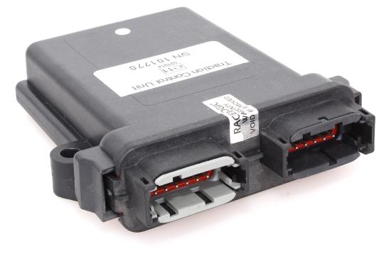
Racelogic Traction Control ECU Tip: The Injector Interface Loom plugs in to the light grey socket on the left. The Comms Loom plugs in to the Black socket on the right. |
 |
|
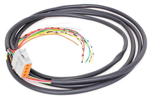
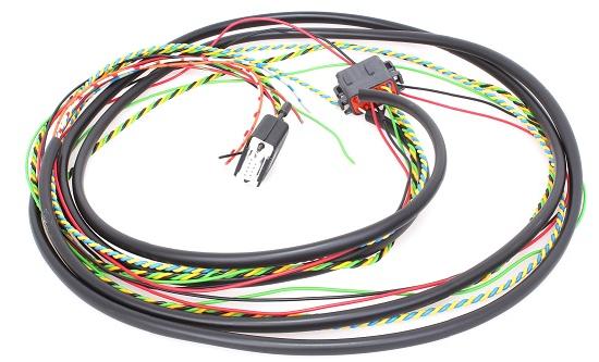
Injector Interface loom (Light Grey Connector) Tip: Wire connections from the vehicle ECU to each injector need to be cut. Single colour wires in the Injector Interface Loom connect to the signal wires from the vehicle ECU. Corresponding coloured wires with a black tag in the Injector Interface loom connect to the signal wires to the fuel injector. |
 |
|
Comms Loom (Black Connector) Tip: Red Wire (Power) – Recommended to use the same 12v source the vehicle ECU uses to prevent the voltage grounding out during cranking. Black Wire – Ground. Female 9 pin D-Type connector – Plug in to Male 9 pin D-Type connector from Digital Adjuster. Yellow Wire (CAN High) and Blue Wire (CAN low) twisted pair – Connect to vehicle’s CAN High and CAN Low wires. Green Wire – Switch Input. Connect to Green POT signal wire from the Digital Adjuster. Green/Red & Grey/Blue – Injector output 7&8 White/Red & Orange/Red – Injector input 7&8 |
 |
|
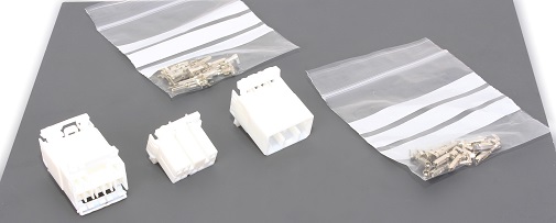
Accessory Pack Tip: It is highly recommended that the installer uses the connector blocks for the injector interfaces. The Connector blocks and pins to allow the user to interface with the fuel injectors in such a way that it’s very quick and easy to put the vehicle back to standard. |
 |
|
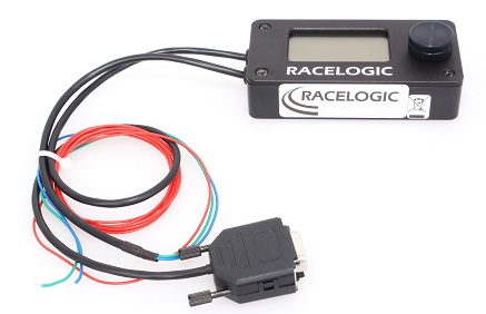
Digital Adjuster Tip: Red Wire – Connect to a reliable 12v switched live, like the stereo power for example. Male 9pin D-Type connector – Plug in to Female 9pin D-Type connector from the Comms loom. Blue Wire – Ground. Green Wire – Adjuster knob potentiometer. Connect to the Green switch input wire from the Comms loom. |
 |
RLTC Fuel Injector Cuts
Injector cuts work by taking the signal supplied to each fuel injector and feeding it into the Racelogic Traction Control System. Under normal running, the signal is exactly reproduced, firing the fuel injectors as normal. When wheel spin is detected the traction control shuts down each fuel injector independently reducing the power of the engine progressively. The severity of the cut is dependent upon the amount of wheel spin detected and the parameters held within the Traction Control Unit.
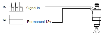
By inspecting the fuel injectors of your vehicle you will see that two wires are connected to each one. One of the wires supplies +12 V whereas the other supplies a 12V signal going down to GND to fire the injector. (see Diagram ). It is these “signal” wires that have to be located and connected to the Traction Control.
The signal and 12V wires have to be connected to the correct pin of the fuel injector so you have to find the “polarity” of the fuel injection system before fitment. The polarity can be identified using a number of methods.
- Wiring Diagrams - If you have a wiring diagram of the vehicle trace each of the signal wires from the engine control unit (ECU) to each of the fuel injectors, the wiring diagram will normally indicate colour codes. The 12V feed wires will be linked together and will generally have a common colour code. If you have books such as the “Autodata - Fuel Injection” series these can help in identifying the polarity of a vehicles fuel injection system.
- Colour Coding - If you have no wiring diagrams you can identify the polarity by looking at the wiring to the fuel injectors. If each of the fuel injectors is fed by a common wire of one colour this will be the 12V feed, the remaining wires should all be different colours and will be the signal wires.
- Continuity Testing – On the majority of cars the 12V side of the fuel injectors are linked together. Place the multi-meter on one injector and check with the next injector, if one side continuity beeps back check the rest of the injectors. Make sure the ignition is off when performing this test.
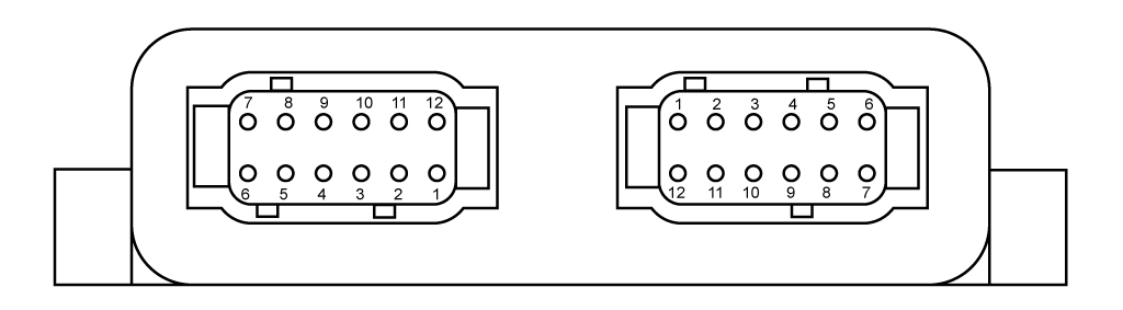
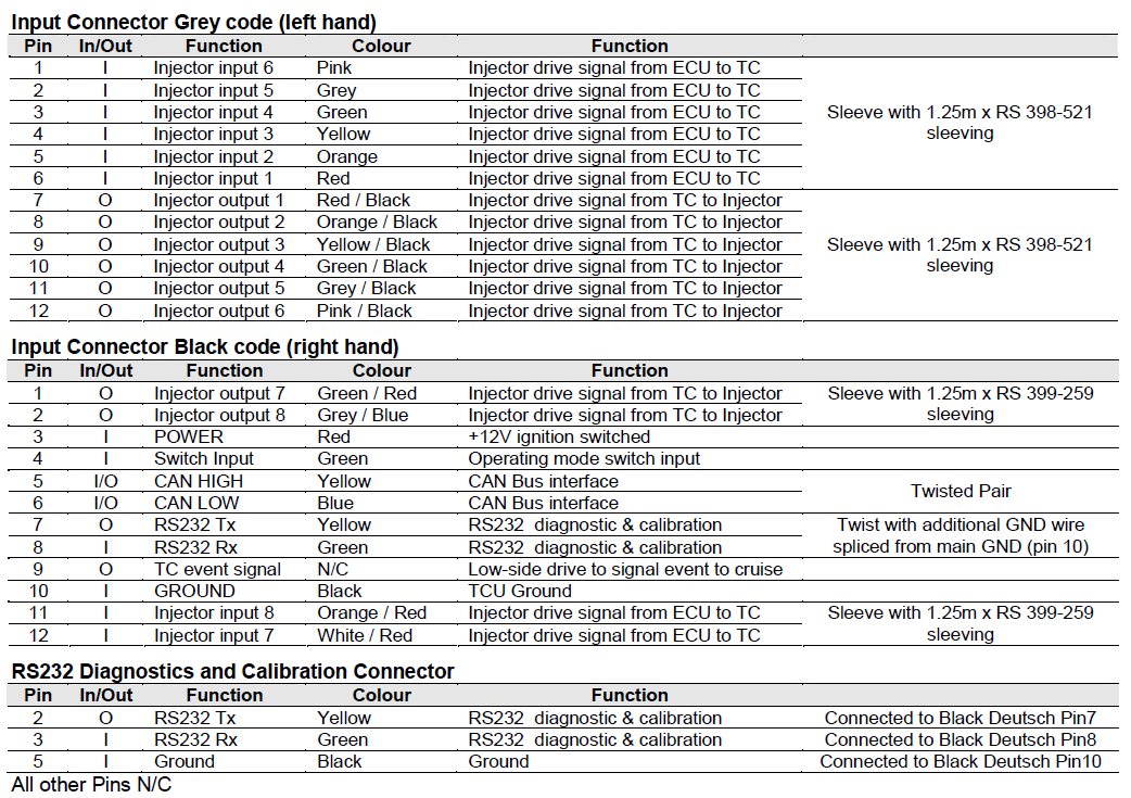
RLTC-CAN Pinouts Diagram