NTRIP Modem RLACS250 - Modem Configuration

This product has been discontinued.
Introduction
These instructions outline the configuration method for the Racelogic NTRIP Modem RLACS250. Ensure that the SIM Card Pin has been disabled before use.
Requirements
- VBOX3iSLR
- Windows PC or Tablet
- NTRIP Modem Cable RLCAB139
- NTRIP Modem Configuration Cable RLCAB140
- NTRIP subscription
- Racelogic NTRIP Modem RLACS250
- Activated SIM card with Mobile Data enabled
Properties
Specification
Power |
|
|---|---|
| Input | 7 V DC to 24 V DC |
| Consumption | 12 V DC: 75 mA; 18 V DC: 50 mA |
Antenna |
|
|---|---|
| Connection | FME M 50 Ω antenna connector |
Wireless module features |
|
|---|---|
| Bands | Quad-Band (850/9000/1800/1900 MHz) |
| Five Bands UMTS (WCDMA/FDD) 800, 850, 900, 1900 and 2100 MHz | |
Environmental and Physical |
|
|---|---|
| Size (l x w x h) | 76 mm x 56 mm x 25 mm |
| Extended temperature range | -40 °C to +75 °C |
| Weight | 100 g (2.5 oz) |
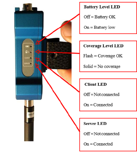
LED Functionality
|
Battery Level LED
|
 |
|
Coverage Level LED
|
|
|
Client LED
|
|
|
Server LED
|
Installing SIM Card
|
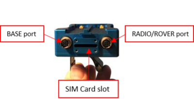
Remove the SIM card cover using the supplied Torx Key |
 |
|
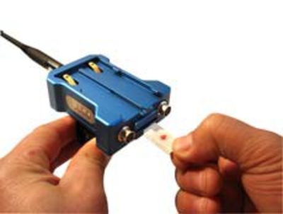
Insert the SIM card into the slot |
 |
|
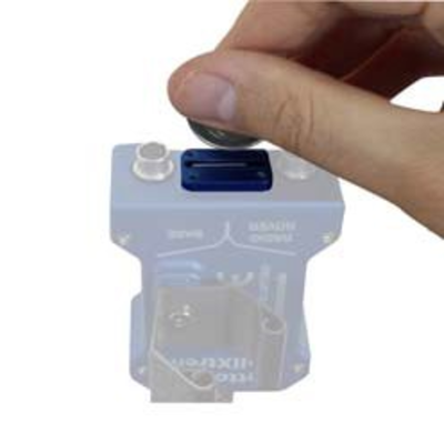
If you need to swap the SIM card, use a coin. Please do NOT use a screwdriver |
 |
Hardware configuration
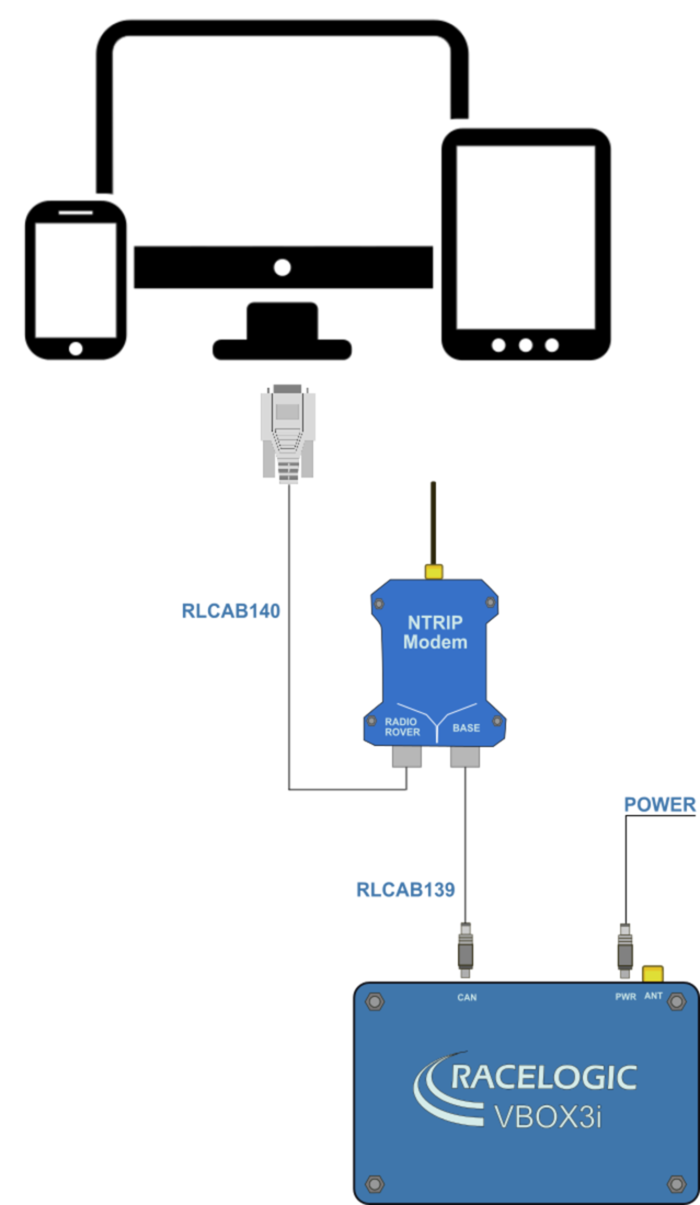
Use the RLCAB139 to supply power to the NTRIP modem by connecting it to the CAN port on VB3iSLR and the BASE Port on the NTRIP Modem.
Connect the RLCAB140 to the RADIO/ROVER port of the NTRIP Modem to the Serial Port or the USB-Serial Adapter of the PC or Tablet.
Modem Configuration
Ensure that the power is supplied to the modem and connected to the Windows PC or Tablet as shown above.
Download and run the modem configuration software available from here. Select the PC COM port that is connected to the Modem.
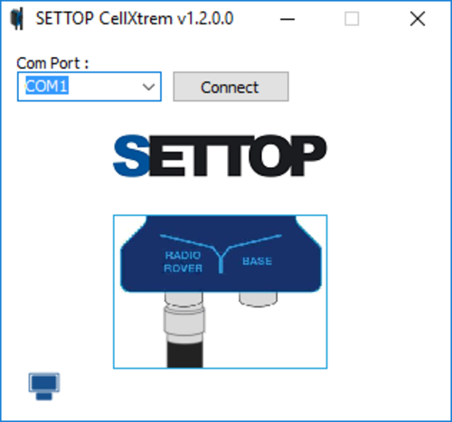
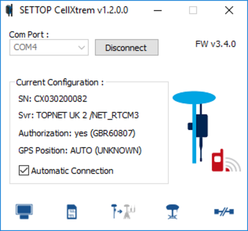
The application will scan at different baud rates to automatically identify the Modem and display the current setup of the device on screen. An example of a correctly working modem connected to the NTRIP server is shown below.
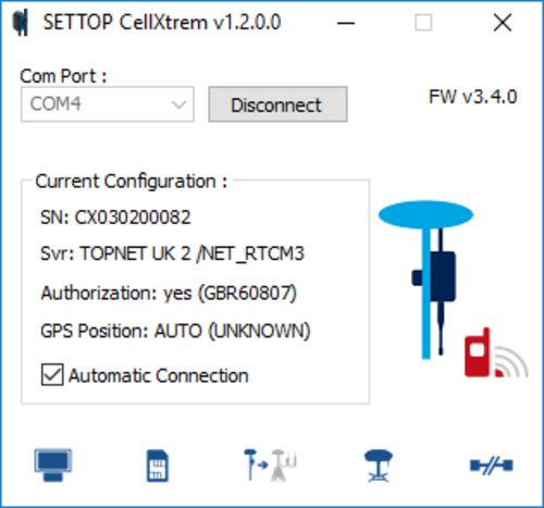
 Is a graphic display of the coverage level. The color indicates the coverage level. (blue >75 %, green 26 to 75 %, red < 25 % and grey 0 %).
On the lower bar, there are a series of buttons (see below) which are used to configure the modem. The configuration process involves starting from the left button to the right.

 Casters list: This button displays a list of all of the available previously configured NTRIP servers, along with the usernames and passwords of NTRIP accounts.
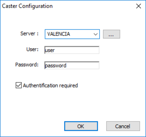
By pressing the edit button  , the details can be edited, deleted or new servers can be added.
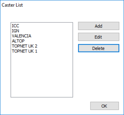
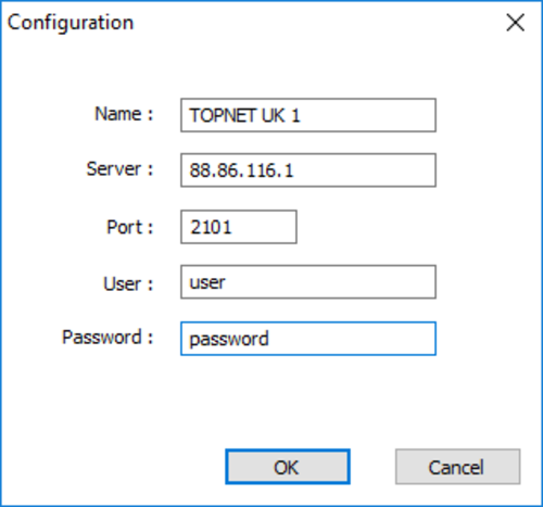
To add a server, click 'Add'. The fields required for connection include the Name, IP address, port, user and password. These details will be provided by your NTRIP service provider, below is an example configuration.
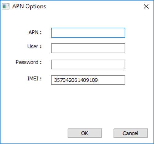
 Operator: This allows the configuration of the Modem to suit the APN Settings in different countries with cellular providers. You should contact the SIM card provider to get these settings. You can also use this website http://wiki.apnchanger.org/Main_Page to find these details.
 Server to Client: Pressing this button will change the configuration from 'Client' mode to 'Server' Mode or vice versa and will update the image on this button. Ensure that the button is set as shown here.
 GPS: This configures the baud rate between the Modem and VB3iSLR. The settings below should be applied.
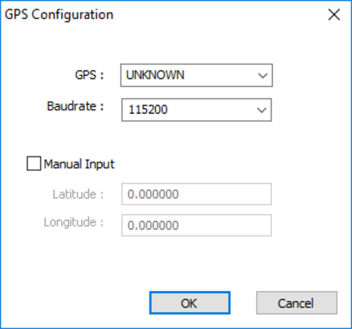
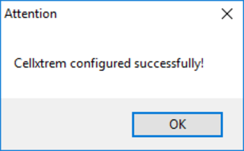
When the 'OK' button is pressed and the settings are updated, 'The NTRIP modem will restart' message will appear.
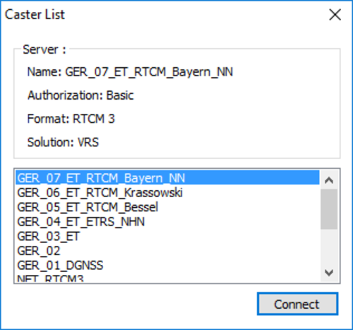
 Connection: This button enables the connection to the NTRIP server. If mobile coverage is available and the Caster setup is correct, a list of Mount Points will be available for the user to select as shown below. Check which Mount Points are available from your NTRIP service provider. The correction messages required in VB3iSLR will be RTCMv3. Once the mount point is chosen, the software will require restarting.
Now that the Modem configuration is complete, click the check box for 'Automatic Connection'. The modem will now automatically connect to the NTRIP server after the Modem is powered on, the VB3iSLR DGPS Mode and Baud Rate are setup correctly and there is mobile coverage and satellite reception.
How to find the TopNET Live server address
If you have not been given the NTRIP Caster Settings, you can install the TopNET live mobile application here and search for them.
https://play.google.com/store/apps/details?id=navmatix.android.tlmmobile
- Click on the key symbol in the top right and enter your TopNET subscription Username and Password.
- Once logged in click on the network information box at the top.
- Make a note of the server IP address and port number. (Currently 88.86.109.135 and 2101 are correct for the UK)
- Exit and close the TopNET live Mobile app.
