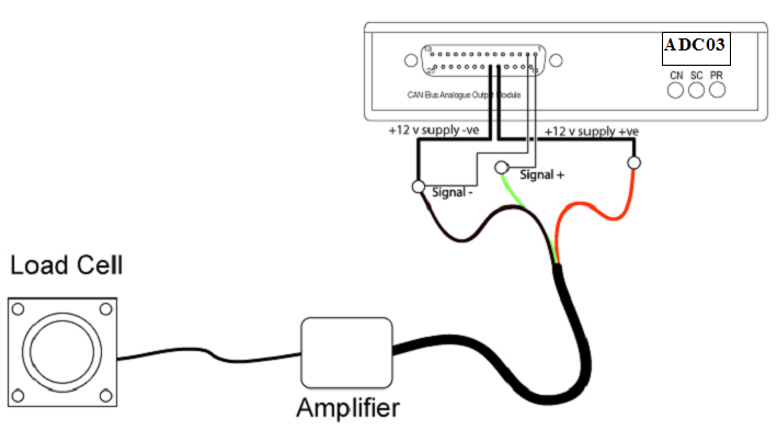
Example load cell connection


In the example shown in PIC6, a load cell is fitted to the ADC03. The load cell is supplied complete with an amplifier module that is calibrated to give an output of approximately 5volts for a full load of 50 Kg. The amplifier has 3 wires (ground, 12v supply and output signal) and these are connected to the ADC03 as shown. The Isolated 12v supply from the ADC03 is used to power the load cell amplifier while channel 1 +ve is used to read the output signal. The channel 1 -ve pin (pin 2) must be connected to the –ve 12v supply pin (pin 19) as a reference for the signal voltage.
The sensor calibration data in this case is shown in the table below.
| Load Applied (kg) | Output Voltage |
|---|---|
| 0 | 0.530 |
| 10 | 1.311 |
| 20 | 2.185 |
| 30 | 3.070 |
| 40 | 4.014 |
| 50 | 4.956 |
Using the ADC03 channel setup, the scale and offset can be entered so that the output for ADC03 channel 1, and hence the data logged by the VBOX, represents Kg load rather than volts. From the calibration data it can be seen that there is a zero load offset of 0.53v. The scale is therefore calculated as:-
.png?revision=1)
The offset value is added after the scale function is performed and so is represented in Kg. Offset in this case is calculated as:-
.png?revision=1)
Because the voltage offset is +0.53v, the offset amount must be negative. Therefore a value of –5.987 is entered as the offset for the ADC03 channel.
