Getting Started
What is in the box?
When you purchase a Visual Sensor, you will find the following items when you open the box:
| Product Code | Quantity | Description | |
|---|---|---|---|
| RLADAS-VS-V1/ RLADAS-VS-V2 |
1 | Visual Sensor with unterminated flying lead (5 m) | 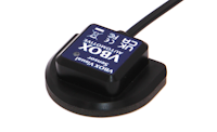 |
Optional Accessories
| Product Code | Description |
|---|---|
| ADC25IPCON | 25-way D-connector |
| SUBCON15M-SH | 15-way D-connector |
Power Supply
The Visual Sensor has a flying lead with an unterminated end. You can wire the exposed wires at the unterminated end of the cable to a 25-way D-connector independently or alongside other sensors. It can also be wired into the 25-way D-connector on the RLCAB119 cable used to connect IMU units to VBOX 3i units.
When you have completed the wiring, you can connect the 25-way D-connector to the A IN port on a VBOX 3i unit, which will provide power to the Visual Sensor.
See the Installing the Visual Sensor page for more information about wiring and connections for the Visual Sensor.
LED Behaviour
The red LED on the top of the sensor will turn on when the sensor detects a light source.