Using VBOX 3iS for Brake Stop Testing
Introduction
Modern electronically controlled braking systems are extremely efficient and are very close to reaching the optimum braking distances for a given tyre and road surface. It is therefore essential that the measurement of braking distances can be carried out with very high distance accuracy.
VBOX 3iS can be used to conduct two main kinds of brake stop testing; Speed Window Tests - The distance travelled between two speeds is measured and Brake Trigger Tests - The distance travelled from the point the brakes are pressed to a standstill.
Configuration
It is necessary to ensure VB3iS is optimally configured for brake stop testing, please follow the instructions below.
Brake Stop Test Setup
Before stop testing commences, ensure that the VB3iS unit is correctly configured for the type of brake stop being conducted.
Speed Window Tests
Define the speed window via the VBOX Setup Software, the Front Panel of the unit or using the VBOX Manager.
VBOX Setup Software
- Ensure VB3iS is powered.
- Connect VB3iS to a computer using the supplied loom, connect an RLCAB001 cable to the 'CONFIG' lead and connect the serial plug to the computers serial port – this can be done via a serial > USB convertor if required.
- Open VBOX Setup and connect to VB3iS by selecting the correct COM Port.
- Select the 'Tests' menu and then the 'Brake' tab.
- Choose a braking speed range by setting a 'Start speed' and 'End speed' (set as 100 km/h and 0 km/h by default).
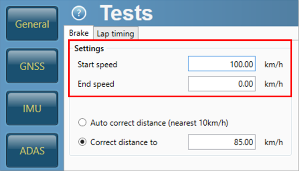
- Select 'Write to unit' to save the settings.
Front Panel
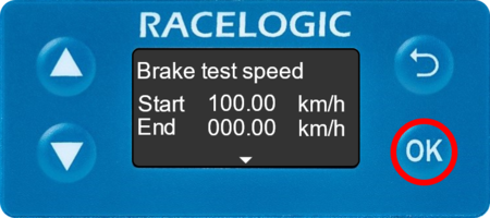
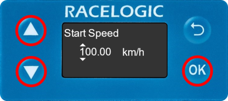
- Press the 'OK' button to enter the menu, navigate to 'Tests' using the 'Down' arrow and then press the 'OK' button.
- Press the 'OK' button again to enter the 'Brake test speed' menu.
- Use a combination of the 'Up' and 'Down' arrows and the 'OK' button to enter the Start and End speeds (set as 100 km/h and 0 km/h by default).
 |
 |
Brake Trigger Tests
Ensure the RLCAB129 loom is being used and connect the Brake Trigger to the 'DIG IN' lead. Ensure that the brake trigger is selected as the digital input via the VBOX Setup Software, the Front Panel of the unit or using the VBOX Manager.
VBOX Setup Software
- Ensure VB3iS is powered.
- Connect VB3iS to a computer using the supplied loom, connect an RLCAB001 cable to the 'CONFIG' lead and connect the serial plug to the computers serial port – this can be done via a serial > USB convertor if required.
- Open VBOX Setup and connect to VB3iS by selecting the correct COM Port.
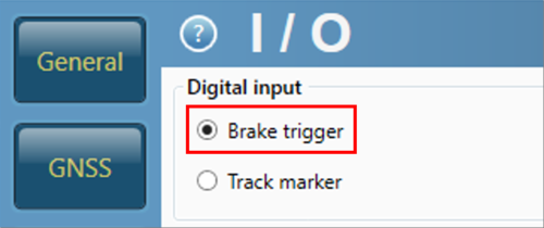
- Select the 'Digital I/O' menu and then ensure that 'Brake trigger' is selected as the 'Digital input'.
- Select the 'Tests' menu and then the 'Brake' tab.
- Enter either a 'Correct distance to' value or select 'Auto correct distance'. These options will correct the trigger start speed, more information is available here.
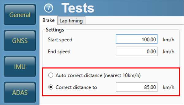
- Select 'Write to unit' to save the settings.
Front Panel
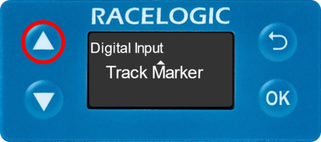
- Press the 'OK' button to enter the menu, navigate to 'Digital I/O' using the 'Down' arrow and then press the 'OK' button.
- It will display whichever mode has been previously set.
- To change the setting, press the 'OK' button then select 'Brake Trigger' using the 'Up' arrow.
 |
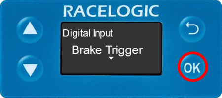 |
- Press the 'OK' button again to confirm.
- Press the 'Back' button and then navigate to the 'Tests' using the 'Down' arrow, press the 'OK' button to enter the menu.
- Navigate to 'Corrected Dist.' using the 'Down' arrow, press the 'OK' button to enter the menu.
- Use a combination of the 'Up' and 'Down' arrows and the 'OK' button to enter a value or select 'Auto'. These options will correct the trigger start speed, more information is available here.
Wheel Speed Inputs
When conducting brake stops, it is vital that wheel speeds are not used!
Within a brake stop, there are higher levels of wheel slip (lock) than in normal driving. If wheel speeds are used, this would be reflected in the Kalman Filter speed which would result in an incorrect braking distance.
Wheel speed input can be 'Disabled' via the VBOX Setup Software, the Front Panel of the unit or using the VBOX Manager.
VBOX Setup Software
- Ensure VB3iS is powered.
- Connect VB3iS to a computer using the supplied loom, connect an RLCAB001 cable to the 'CONFIG' lead and connect the serial plug to the computers serial port – this can be done via a serial > USB convertor if required.
- Open VBOX Setup and connect to VB3iS by selecting the correct COM Port.
- Select the 'IMU' menu and then the 'Wheel speed input' tab.
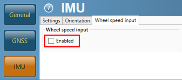
- Ensure wheel speed input is 'Disabled' (unticked).
- Select 'Write to unit' to save the settings.
Front Panel
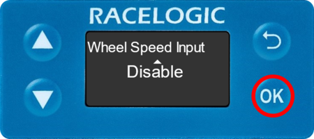
- Press the 'OK' button to enter the menu, navigate to 'IMU' using the 'Down' arrow and then press the 'OK' button.
- Navigate to 'Wheel Speed Input' using the 'Up' and 'Down' arrows. It will display whichever mode has been previously set.
- To change the setting, press the 'OK' button and then press the 'OK' button again to confirm.
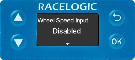
- 'Disabled' will then be displayed.
 |
 |
Dynamic Mode
The dynamic mode should be set as 'High', this can be done via the VBOX Setup Software, the Front Panel of the unit or using the VBOX Manager. More information on Dynamic Modes is available here.
VBOX Setup Software
- Ensure VB3iS is powered.
- Connect VB3iS to a computer using the supplied loom, connect an RLCAB001 cable to the 'CONFIG' lead and connect the serial plug to the computers serial port – this can be done via a serial > USB convertor if required.
- Open VBOX Setup and connect to VB3iS by selecting the correct COM Port.
- Select the 'GNSS' menu and then the 'Settings' tab.
- Select 'High dynamics' from the 'GNSS optimisation' options.

- Select 'Write to unit' to save the settings.
Front Panel
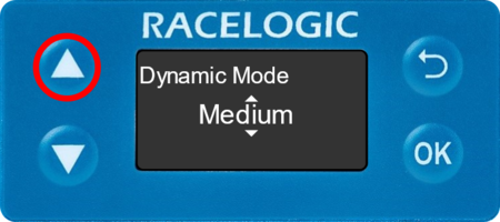
- Press the 'OK' button to enter the menu, navigate to 'GNSS' and press the 'OK' button.
- Navigate to 'Dynamic Mode' using the 'Up' and 'Down' arrows. It will display whichever mode has been previously set.
- To change the setting, press the 'OK' button then select 'High' using the 'Up' arrow.
 |
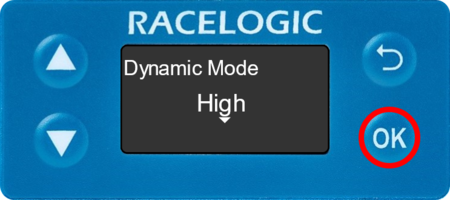 |
- Press the 'OK' button again to confirm.
IMU Integration
If you are conducting a Speed Window Test, IMU Integration can be 'Enabled' to eliminate the potential overshoot, this can be done via the VBOX Setup Software, the Front Panel of the unit or using the VBOX Manager.
Once IMU Integration has been Enabled, it is important to perform the full calibration procedure before meaningful testing commences. The calibration procedure is a series of specific manoeuvres that should be performed to help the Kalman Filter characterise the outputs from the IMU. More information on this is available here.
VBOX Setup Software
- Ensure VB3iS is powered.
- Connect VB3iS to a computer using the supplied loom, connect an RLCAB001 cable to the 'CONFIG' lead and connect the serial plug to the computers serial port – this can be done via a serial > USB convertor if required.
- Open VBOX Setup and connect to VB3iS by selecting the correct COM Port.
- Select the 'IMU' menu and then the 'Settings' tab.
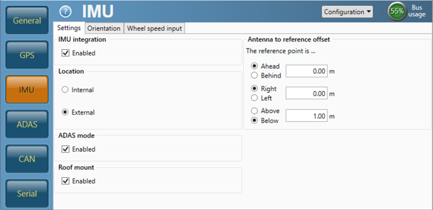
- Select 'Enabled' within the 'IMU integration' section.
- If you are using an External IMU, select 'External' within the 'Location' section. If you are using a roof mounted IMU solution, ensure Roof mount is 'Enabled'.
- Enter the Antenna to IMU/ reference offsets, more information on this is available here.
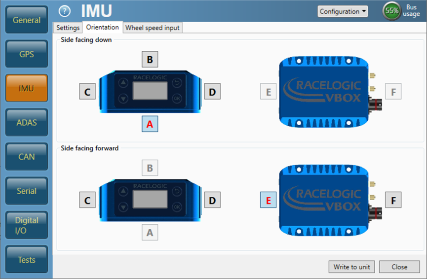
- If the Internal IMU is being used, select the 'Orientation' tab and ensure that the sides of the unit facing down and forward are indicated correctly.
- Select 'Write to unit' to save the settings.
Front Panel
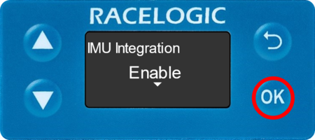
- Press the 'OK' button to enter the menu, navigate to 'IMU' using the 'Down' arrow and then press the 'OK' button.
- Press the 'OK' button again to Enable IMU Integration.
- 'Enabled' will then be displayed.
 |
 |
- If you are using an External IMU, navigate to 'IMU Location' using the 'Down' arrow and press the 'OK' button. Use the 'Down' arrow to select 'External' and press the 'OK' button to confirm. If you are using a roof mounted IMU solution, ensure Roof Mount is 'Enabled'.
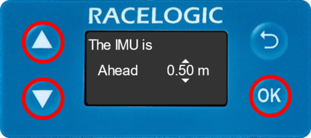
- Navigate to 'Ant to IMU/Ref. Offset' using the 'Down' arrow, press the 'OK' button to enter the menu. Use a combination of the 'Up' and 'Down' arrows and the 'OK' button to enter the measured ahead/behind, right/left and above/below offset values, more information on this is available here.
 |
 |
- If the Internal IMU is being used, navigate to 'Side facing down' using the 'Down' arrow and press the 'OK' button to enter the menu. Use the 'Up' and 'Down' arrows to ensure the correct side is indicated and press the 'OK' button to confirm. Repeat for 'Side facing forwd'.