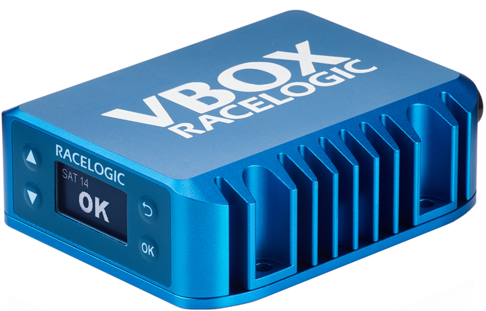
01 Getting Started - VBOX 3iS Single Antenna RTK (v1)
Registration
Please register your VBOX 3iS Single Antenna RTK unit so that Racelogic can continue to provide you with notifications about the latest software releases and firmware upgrades for your Racelogic product and offer technical support.
Register your device here.
What is in the box?
 |
| RLVB3ISR-V1 |
|---|
| Product Code | Quantity | Description |
|---|---|---|
| VB3ISR-V1 | 1 | VBOX 3iS 100 Hz GNSS system with Inbuilt IMU and RTK - Unit Only |
| RLACS156 | 1 | GPS/Glonass Low Profile Antenna - 4m |
| RLCAB128/ RLCAB129/ RLCAB130 |
1 | Cable loom (each option is for a specific use, as selected when ordered) |
| RLACS106 | 1 | VBOX Plastic Carry Case |
| RLCAB001 | 1 | Lemo 5W Plug - 9W D Socket - 2m cable (Serial Configuration) |
| RLCALUKAS | 1 | Certificate of Calibration |
Note: You may have to order additional cables separately
Power Supply
VBOX 3iS units are powered via the POWER and GROUND leads or the CAN + POWER lead on the supplied loom. You can power VBOX 3iS from a wide range of voltage sources. The maximum operating voltage input must not exceed 30 V DC. Failure to observe this could result in damage to the VBOX unit.
VBOX 3iS has been designed to generate as little heat as possible and it has a wide operating temperature range. It is, however, good practice to mount it in a position where it has sufficient airflow around the case.
IMPORTANT
- You must connect the GNSS antenna before you connect power to the VBOX 3iS.
- Compatible cable looms will have the same colour as the colour marker on the unit's connector. VBOX 3iS Single Antenna (v1) has a red colour marker.
Cable Loom
RLCAB128
Speed sensor with IMU - Speed-only cable
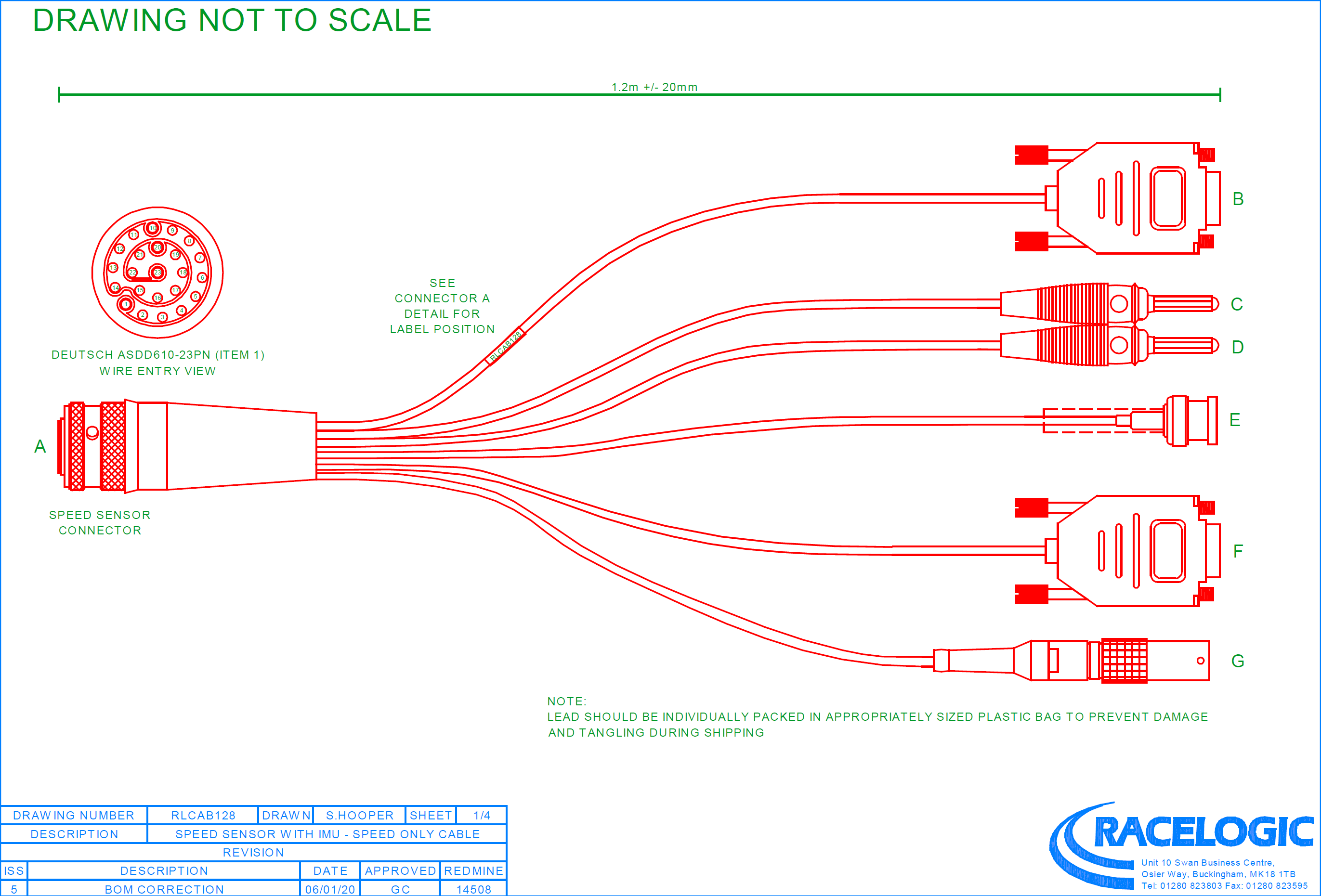
| Cable | Function | Cable | Function |
|---|---|---|---|
| A | UNIT CONNECTOR | E | DIGITAL OUT |
| B | CONFIG | F | CAN |
| C | POWER | G | CAN OUT + POWER |
| D | GROUND |
RLCAB129
Speed sensor with IMU - Braking Cable

| Cable | Function | Cable | Function |
|---|---|---|---|
| A | UNIT CONNECTOR | E | DIGITAL IN |
| B | CONFIG | F | CAN IN |
| C | POWER | G | CAN OUT + POWER |
| D | GROUND | H | EXTERNAL IMU |
RLCAB130
Speed sensor with IMU - ADAS cable
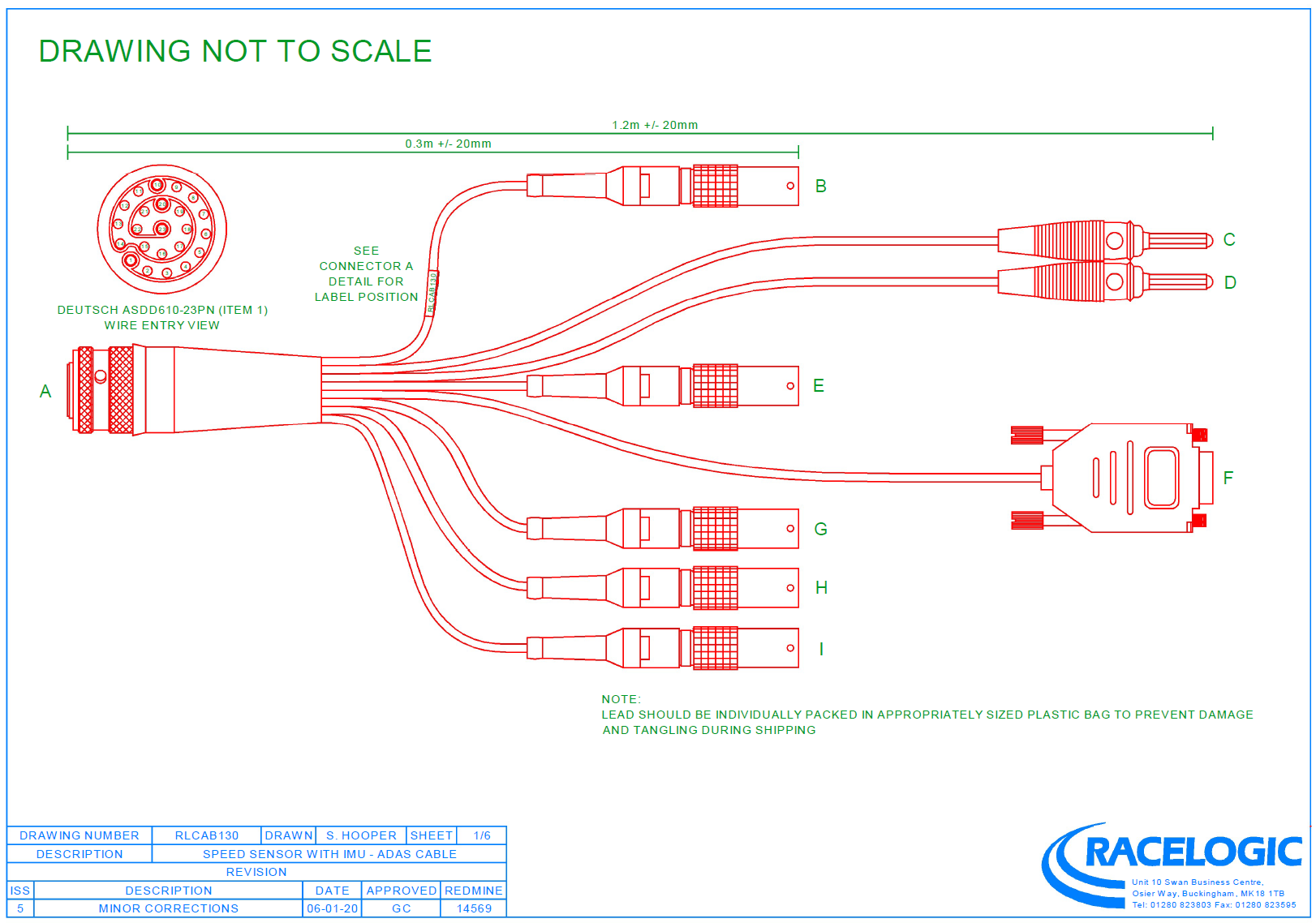
| Cable | Function | Cable | Function |
|---|---|---|---|
| A | UNIT CONNECTOR | F | CAN IN |
| B | SERIAL | G | CAN OUT + POWER |
| C | POWER | H | EXTERNAL IMU |
| D | GROUND | I | DGPS |
| E | DIGITAL IN |