IMU
This page contains an overview of the features and settings in the IMU Menu in VBOX Setup connected to VBOX 4 Dynamics.
IMU Integration

Settings
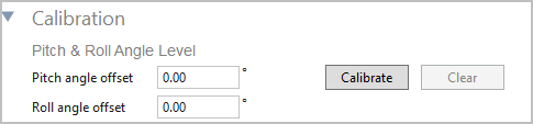
Calibration
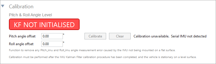
Pitch & Roll Angle Level

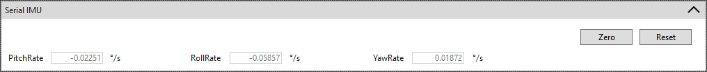
Zero Gyro Rates
|
These rate offsets are used to correct any gyro bias, making the Pitch, Roll and Yaw channels read zero when the vehicle is stationary. You can expand the Serial IMU section to view the live values for Pitch Rate, Roll Rate and Yaw Rate and to find the Zero function for the Gyro Rate Offsets.
Click the Zero button to calibrate the rate offsets for all detected and available IMUs. The software will run through an auto-calibration procedure for each available IMU.
Click the Reset button to remove the calibrated offsets and reset the rates to the default values.
|
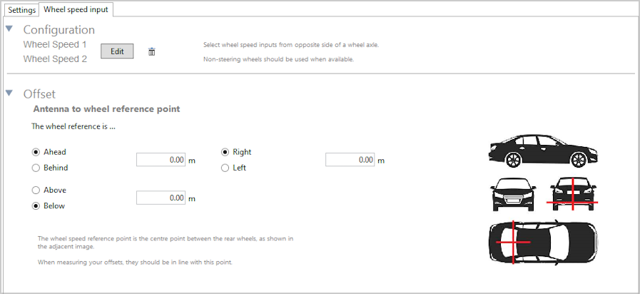
Offset
|
|

Wheel Speed Input

|
|
Configuration
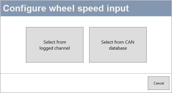
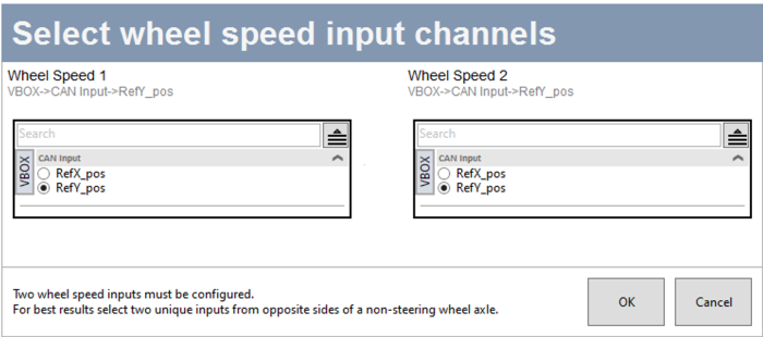
Select From Logged Channel
|
|
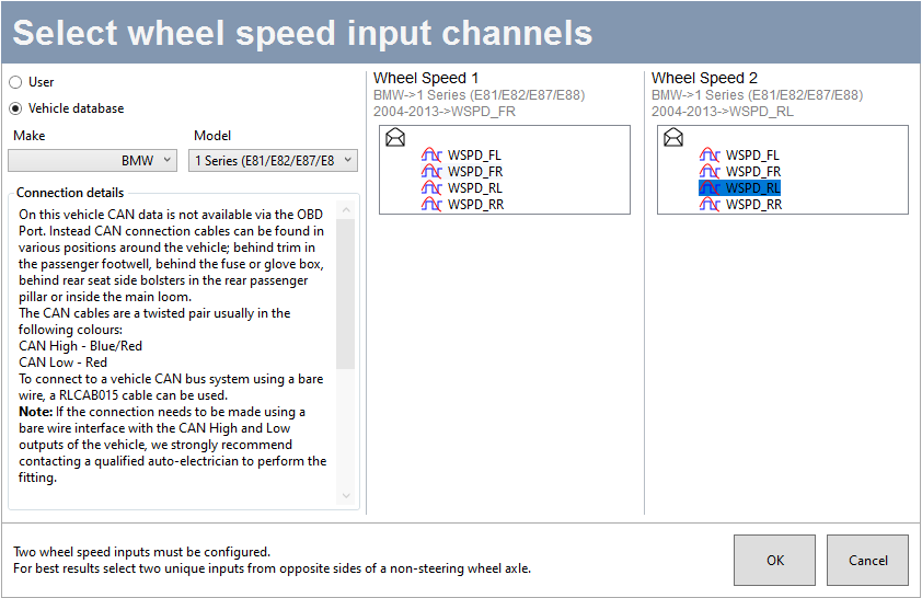
Select From CAN Database
|
|
Offset
|
|