VBOX II PIN OUTS

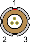
Connector 1 - POWER (Lemo 2 PIN)
(Dedicated 4.5 – 36 V DC Power Connector)

| PIN | I/O | Function |
|---|---|---|
| 1 | I | Power+ |
| 2 | I | Ground |
| Chassis | I | Ground |
Connector 2 / 3 - OUT 1 / OUT 2 (Lemo 3 PIN)
(One Analogue and One Digital Output Each)
| PIN | I/O | Function |
|---|---|---|
| 1 | O | Analogue Out 1 / 2 |
| 2 | O | Digital Out 1 / 2 |
| 3 | I | Ground |
| Chassis | I | Ground |
Connector 4 - DIG I / O (Lemo 3 PIN)
(Wheel Speed and Brake Trigger Inputs)
| PIN | I/O | Function |
|---|---|---|
| 1 | I | NC |
| 2 | I | NC |
| 3 | I | Brake Trigger |
| Chassis | I | Ground |
Connector 5 - CAN (Lemo 5 PIN)
(First CAN Bus Connector, Serial Connection to GPS Engine)
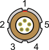
| PIN | I/O | Function |
|---|---|---|
| 1 | O | RS232 Tx GPS (Tx Data from GPS engine) |
| 2 | I | RS232 Rx GPS (Rx Data to GPS engine) |
| 3 | I/O |
CAN High |
| 4 | I/O |
CAN Low |
| 5 | I/O | Power + |
| Chassis | I | Ground |
Connector 6 - SERIAL (Lemo 5 PIN)
(Setup / Upgrade, Second CAN Bus Connector)
| PIN | I/O | Function |
|---|---|---|
| 1 | O | RS232 Tx GPS (Tx Data from GPS engine) |
| 2 | I | RS232 Rx GPS (Rx Data to GPS engine) |
| 3 | I/O |
CAN High |
| 4 | I/O |
CAN Low |
| 5 | I/O | Power + |
| Chassis | I | Ground |
Connector 7 - USB
(Setup / Upgrade)
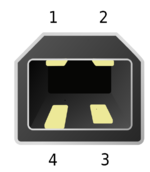
| PIN | I/O | Function |
|---|---|---|
| 1 | I/O | Power |
| 2 | I/O | USB- |
| 3 | I/O | USB+ |
| 4 | I/O | Ground |
| Chassis | I/O | Ground |
Connector 8 - GPS Antenna

| PIN | I/O | Function |
|---|---|---|
| 1 | I | Signal |
| Chassis | I | Ground |