02 - VBOX Tools Configuring the VBOX and Modules
To configure a VBOX datalogger or VBOX speed sensor, the VBOX needs to be connected to a power source and a PC. (Please refer to the VBOX User Guide for details of the RS232 serial connection).
Please note that the setup options available will vary between units, particularly for VBOX speed sensors. The VBOX Mini has no on-screen configuration options (only information about the unit is shown) but the VBOX Setup facility can be used for configuration of a VBOX Mini Input Module when attached to the VBOX Mini.
Enter the VBOX Setup screen by clicking on the ‘VBOX Set-up’ button in the Main Button bar.

Or Selecting ‘VBOX Setup’ from the ‘VBOX ‘ option of the main Menu bar.
.png?revision=1)
A new window will appear like the screen shown below. The example shown is the standard setup window of a VBOX 3i SL, so in addition to the standard channels available there are also Internal A/D and VCI Modules channels shown with their own tabs.
If a VBOX CAN module is connected then a dedicated tab will also appear in the same row as the standard channels tab.
.png?revision=1)
The main Button bar of this window contains six icons that give access to all the VBOX setup options.
NB: A VBOX with Slip Angle (VBS20SL, VB20SL & VB20SL3) can be configured either as a VBOX module or in a similar way to a VBOX, depending on the mode of operation at the time.
Channels
Standard Channels
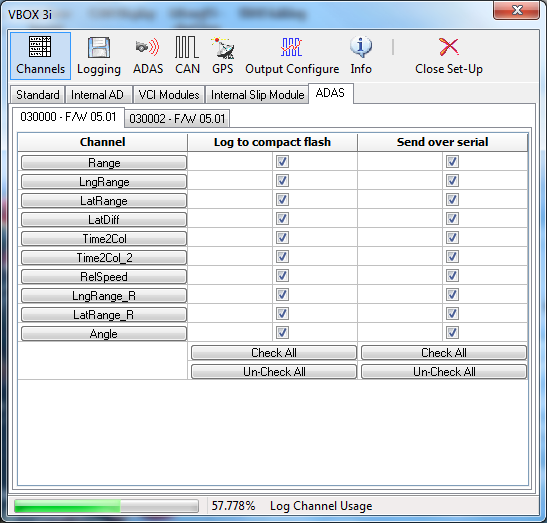
The first screen, ‘Channels’, shows which GPS parameters are enabled for logging to compact flash. The default channels, that are locked to log to compact flash are:
|
|
These main channels are locked to prevent important channels that are key to additional analysis from not being logged. For example, the satellite channel also contains data from the brake trigger, the latitude/longitude are required to plot the vehicle’s path, and the heading is necessary to calculate lateral acceleration.
The bandwidth status bar ‘Log Channel Usage’ at the bottom gives an indication of available logging bandwidth. When the status bar is full, all of the bandwidth is used; if more logging channels are added beyond this, there is a risk that data will be lost. The bandwidth status bar is calculated for a speed optimised compact flash card. If a windows formatted card is used, the status bar will be inaccurate with the risk that data may be lost.
The option to enable a channel in the serial data stream is kept as a separate option so that the serial data stream does not become too overloaded. It is often the case that not all logged channels are needed in the serial data stream for live viewing. Note that to add the channel to the serial stream; the channel must also be set for logging to the compact flash card.
Internal Analogue Inputs and Internal VCI (SX, SL, VBIII and VBOX 3i Models Only)
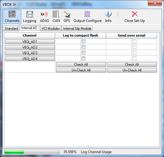
The VBOXIII is equipped with 4 built-in analogue inputs and 8 external CAN channels (VCI). The configuration windows for the analogue and VCI channels on VBOXIII appear alongside the standard channels tab.
|
Clicking on the ‘Internal AD’ tab will display the 4 analogue input channels. Logging of each channel can be turned on or off simply by ticking or clearing the tick box next to each channel name, under ‘Log to compact flash’. Each channel can also be added to the RS232 serial data stream by also clicking the ‘Send over serial’ tick box. |
 |
|
Clicking on the channel name button will display the corresponding channel setup window, left. The native measurement unit for the internal analogue channels is Volts therefore a scale of 1 and offset of 0 corresponds to a live data value in volts. By changing the scale and offset values, the live data reading (and therefore the logged data value) can be calibrated for real sensor values. |
.png?revision=2) |
VCI Modules
Clicking the ‘VCI Modules’ tab will show the number of VCI CAN channels available to that unit. Logging of each channel can be turned on or off simply by ticking or clearing the tick box next to each channel name, under ‘Log to compact flash’. Each channel can also be added to the RS232 serial data stream by also clicking the ‘Send over serial’ tick box.
.png?revision=1)
By clicking on a channel button, the channel setup window will appear. In the setup window it is possible to define the parameters that the VBOX will use to extract a signal from a CAN Frame. The setup window also contains a ‘Database’ icon. Clicking this button allows signal information to be loaded in from an industry standard CAN Database (.dbc) file, or from a Racelogic Database File (.rdf, .vci, & .ref).
.png?revision=1)
External CAN Modules
.png?revision=1)
The VBOXTools creates a tabbed page in the setup window for each input module that it finds. If it finds two modules of the same type (for example, two ADC03s) then it lists each one by its serial number which can be seen on the lower set of tabs. The presence of CAN modules is automatically detected by the VBOX when the VBOX Set-up is run. Each detected CAN module is allocated a tab in the Channels screen.
Configuring a CAN Module
Click on the tab for the CAN module you wish to configure, in the Channels section of the VBOX Set-up window. This will show a window that has a tick box and channel button for each channel of the CAN module.
Clicking on a channel button opens up a channel setup box allowing the user to set the channel name, units of measurement, scale and offset. Once a channel is configured, the settings are stored within the associated module. Also displayed in the channel setup is a real-time view of the data on that channel. The data shown is scaled and offset, so if an ADC02 input channel is connected to a 5V throttle potentiometer and the scale and offset are calibrated for percentage throttle opening, then the live data value will show a reading as a percentage of throttle opening.
.png?revision=1)
Once a channel has been enabled by clicking the tick box, it will then be present in the logged data. For the enabled CAN data to be present in the serial data stream for real time viewing, it will need to be enabled in the ‘Send over serial’ column. Refer to the ‘Serial Output (VBOX III & VBOX 3i Only)’ section for information on serial channel enabling.
For further information on configuring individual Racelogic CAN modules refer to each module’s dedicated manual.
Logging
This screen gives access to the logging settings of a VBOX. The page shown right is the logging page of a VBOX III. The SX, SL, VBOX II and VBOX II Lite models do not have options for a 100 Hz serial data rate or Advanced Log Conditions.
.png?revision=1)
Log Conditions
Only When Moving
When the ‘Only When Moving’ option is selected the VBOX will only log data to the compact flash card when the speed is higher than 0.5 km/h. This mode helps stop compact flash cards being filled with unwanted data.
Continuously
The ‘Continuously’ option causes the VBOX to log all enabled data to the compact flash card continuously.
Advanced
|
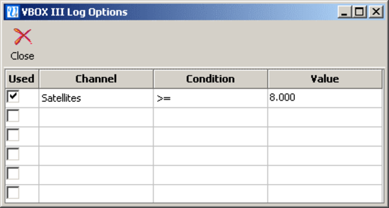
When the ‘Advanced’ option is ticked, a button labelled ‘Advanced’ appears in the Logging window. When this button is pressed you can define the logging conditions, as shown in the window below. Tick the box in the ‘Used’ column to enable that criterion. |
.png?revision=1) |
|
In the ‘Channel’ column any one of the currently logged standard or CAN channels can be selected from a drop down menu, accessed by left-clicking the mouse in the channel box. The ‘Condition’ option allows the selection of the Boolean condition to be applied, from the following options:
The ‘Value’ option allows a threshold value to be entered for the logging condition to apply to. NB: When using Time as a logging threshold the time should be entered in milliseconds. For example the time 14 hrs 35 minutes and 20 seconds would be expressed in milliseconds as 52520000. |
|
.png?revision=1)
Stop Logging Delay
When the Logging option ‘Only When Moving’ and ‘Advanced logging’ options are selected the ‘Stop Logging Delay’ option becomes available. This allows logging to continue for a set period of time even though the vehicle has come to a stop and speed is less than 0.5 km/h. The delay time periods are 1, 2, 5 and 10 seconds.
Compact Flash Log Rate
This option allows the setting of the rate at which data is logged to the compact flash card by the VBOX. The maximum is 5 – 20 Hz for SX/SL models, 20 Hz for VBOX II and VBOX II Lite and 100 Hz for VBOX III and VBOX 3i.
Serial Output
A VBOX III and VBOX 3i can output all enabled Standard and CAN channels at 5 Hz and 20 Hz on the RS232 serial data stream but due to the large amount of data the available data is limited at the higher rates of 50 Hz and 100 Hz.
USB/Bluetooth
On a VBOX 3i all Standard and CAN channels are available through the USB or Bluetooth connections at 100 Hz.
RS232 serial output
In 50 Hz mode all of the standard channels are present in the serial data stream but no CAN channels.
The 100 Hz mode is designed for accurate live data monitoring and analysis of acceleration and brake stop times, distances and acceleration values. In this mode only the channels Satellite, Time, Speed and Trigger event time are present in the serial data stream.
The 5 Hz mode is primarily for sending serial data via low-bandwidth connections. For example, the VBOX Telemetry Modules are optimised to transmit data at this lower serial rate. This lower serial rate ensures that all available channels, including CAN channels, can be transmitted over serial.
Advanced Driver Assistance Systems (ADAS)
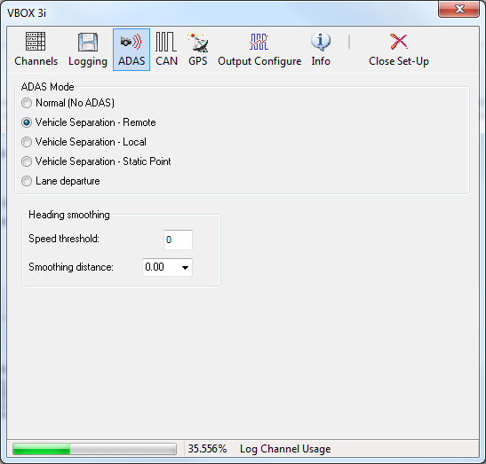
When using VBOX III or VBOX 3i/SL, an additional section appears called “Vehicle Separation”. This allows these VBOX’s to be configured for use in Vehicle Separation mode (as either the remote or local VBOX), to set a static separation point, or to set the VBOX back to normal (non Vehicle Separation) operation. Please refer to the ADAS or VBOX 3i User Manual for more information.
 |
 |
CAN
The CAN screen contains the configuration options for the CAN output of the VBOX. In the case of the VBOX III and VBOX 3i the CAN port socket allocation is controlled from this screen.
Within this page there are three tabbed pages, ‘Config’, ‘Tx Identifiers’ and ‘VBOX 3i CAN Resistor’.
Config
Baud Rate
The ‘Baud Rate’ icon allows the selection of the CAN output data rate from one of the following, 125, 250, 500, 1000 Kbit or ‘Other’. On the VBOX III and VBOX 3i this is applied to the Vehicle CAN Bus output. In the case of SX, SL, VBOXII and VBOXII Lite these baud rate settings are applied to their only CAN port. If a Multi Function Display (MFD) is also being used with the SX, SL, VBOXII or VBOXII Lite the MFD will only work when it also has its baud rate set to the same rate. See the user guide of the MFD for information on setting the MFD baud rate. The MFD’s default data rate is 500kb/s.
To select a baud rate other than the four standard options, click on ‘Other’. In the new screen that appears, enter the approximate value of the baud rate you wish to use along with a suitable tolerance (as a percentage). Click on the ‘Calculate’ button and the software will then display all possible baud rates matching those settings. Select the desired option by double-clicking it.
NB: VBOX units cannot function at all of the baud rates listed, particularly the lower baud rates.
ReScan
When clicked, the ‘ReScan’ icon will force the VBOX to rescan its CAN bus. This can be used if modules are connected or disconnected, allowing a data update without the need to exit and re-enter VBOX setup.
Delete Settings
‘Delete Settings’ causes the VBOX to delete any settings associated with CAN modules.
Racelogic Bus (VBOX III & VBOX 3i Only)
|
This function, the port diagram shown in the centre of the setup window, allows the association of the CAN ports to the CAN and RS232 sockets to be swapped. The ports are swapped by clicking anywhere in the screen image of the CAN and RS232 sockets. The ports will not swap until VBOX Set-up has been exited and in the case of the VBOXIII after it reboots.
The default mode is to have the Racelogic CAN bus (for modules) associated to the CAN socket and the Vehicle CAN bus interface and VBOX CAN output bus associated to the RS232 socket.
This CAN bus swap facility is useful when the VBOXIII/3i is not being used with modules but is being used with a connection to a vehicle CAN bus and also requires connection to a PC via the RS232 serial at the same time. |
 |
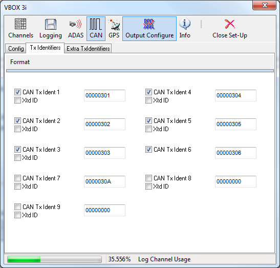
Tx Identifiers
|
The ‘Tx Identifiers’ tab contains the CAN identifiers that are used in transmission of the VBOX data out to the CAN bus. The identifier values can be changed by the user to avoid conflict with other equipment that may also be connected. The tick boxes allow CAN messages to be turned on or off.
On the Secondary CAN port of a VBOXIII the Identifiers can be switched between Standard and Extended by ticking the Xtd ID box. |
 |
CAN Termination
Ability to add CAN termination to either the CAN or RS232 port. Required when other Racelogic units, like the VBOX Manager, are being connected to the VBOX.
GPS
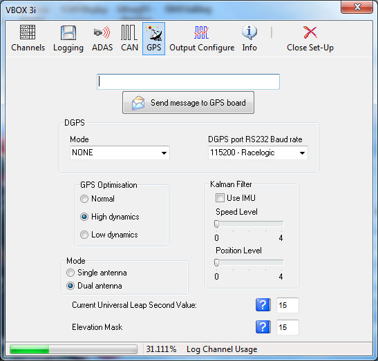
The GPS page contains settings that are relevant directly to the GPS engine inside the VBOX. See individual products manuals for more detailed product specific information.
DGPS
Differential GPS is a facility that increases the absolute positional accuracy of VBOX latitude, longitude and height channels. There are two options available: WAAS DGPS and Local (BaseStation) DGPS.
There are three different levels of positional accuracy available with Local Basestations, the availability of these depends on the version of VBOX and upgrade options that you have purchased.
NB: If a GPS coldstart is performed then the DGPS setting will need to be re-enabled.
WAAS DGPS
This form of DGPS uses the DGPS correction information transmitted by a geo-stationary DGPS satellite. It requires the vehicle to be in view of the nearest DGPS geo-stationary satellite. This improves latitude and longitude positional accuracy from 3m to 1.8m.
Local (BaseStation) DGPS
This form of DGPS uses DGPS correction information transmitted from a Local Base Station GPS unit via radio telemetry. This requires a Racelogic Basestation and radio telemetry unit which increases the Latitude, Longitude and Height accuracies.
Currently there are two types of Basestation available.
- RLVBBS2
- 40cm RTCM correction output applicable to all VBOXIII and VBOXII units
- 20cm correction output applicable only to an upgraded SX, SL, or VBOXIIS
- RLVBBS3
- 40cm RTCM correction output applicable to all VBOX II, VBOX III, and VBOX 3i units
- 2 cm RTK correction output applicable to VBOX III and VBOX 3i RTK models
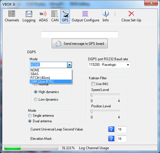
Enabling DGPS
Enabling or Disabling any of the DGPS modes is done via a drop down menu in the GPS page of VBOX setup.
With a VBOXIIS 20cm and 40cm options are available. (20 cm is only available if the VBOX IIS is has a 20cm GPS upgrade option). With a standard VBOX III or VBOX 3i only 40cm is available, with a VBOX III or VBOX 3i RTK, either 40 cm or 2cm is available. In some cases the option for RTK is shown when not available, if the option is selected, a message informs the user that the feature is not available.
 |
 |
Send Message to GPS Board
This function is used to set non-standard settings in the GPS engine. This will generally only be used on advice from a VBOX support technician.
GPS Optimisation
The GPS screen also gives the option to set the Dynamic mode of the VBOX. This option directly changes the SMI smoothing index applied by the GPS engine to all Doppler-derived data, notably speed and heading. The lower smoothing levels have a higher dynamic response but are adversely noisier. The three options are:
|
Normal: |
The ‘Normal’ mode should only be used for any testing that does not involve any high dynamic manoeuvres. |
|
High Dynamics: |
The ‘High dynamics’ setting should be used for high accuracy Trigger Brake Stops or any test where time and distance are critical and the vehicle test incorporates highly dynamic manoeuvres. |
|
Low Dynamics: |
The ‘Low dynamics’ mode is used for smoother velocity and heading data and less acceleration noise only in lower dynamic tests. |
The dynamic mode of a VBOX can be viewed in the live VBOX Summary screen.
Kalman Filter
The real-time Kalman filter is a feature provided within the GPS engine of a VBOX II and as part of the firmware in VBOX III and VBOX 3i. The Kalman filter smoothes the position and speed data in real time in conditions where satellite reception can be varied, such as a heavily tree-lined road, or through a built up area.
For circuit analysis the Kalman filter works very well and stops any positional jumps in the data due to trees or buildings. It also generally smoothes all of the results for easy comparison between files
|
In the VBOX III and VBOX 3i the level of filtering applied to the speed trace and position information can be independently adjusted. If the settings are both set to zero, the Kalman filter will have no influence and is effectively off. This setting is unaffected by a GPS Cold Start on the VBOXIII and VBOX 3i.
In the VBOXII the levels of filtering cannot be adjusted; the Kalman filter can only be enabled or disabled.
Note: Once the filter is turned on, it remains on until it is manually turned off or a GPS Cold Start is performed, even if the VBOX is disconnected from its power supply. NB: This applies to some units only.
It is important to note that the Kalman filter is a real time filter that is carried out on the data as it is written to the flash card or RAM. It therefore cannot be removed if already applied to data. If the nature of your tests involve viewing and analyzing real time data then the built-in real time Kalman filter is recommended.
|
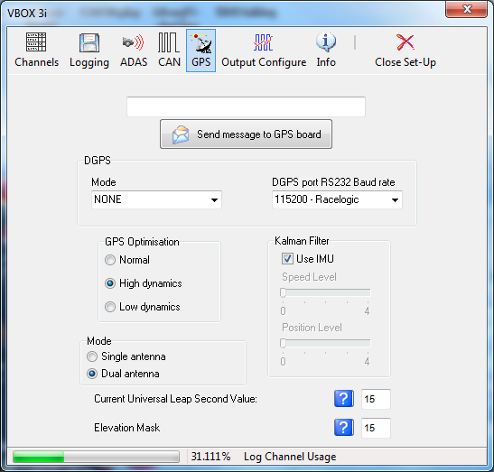 |
VB3i SL Mode
When a VB3i SL is connected to VBOX Tools, when you enter the setup you will be presented with an additional option to toggle between dual and single antenna mode.
Universal Leap Second Value
Due to the slowing rotation of the Earth, a time offset exists between UTC time and GPS time (the time shown as ‘UTC time’ in VBOX data files). This offset is slowly increasing, at a rate of one second every few years.
To correct the time shown in the logged data, update this value with the latest leap second value, available from Racelogic. At the time of writing (Mar 2018), the current offset was 18 seconds.
Elevation Mask
Feature to be used to improve GPS signal quality when nearby obstacles like trees and buildings are reflecting or temporarily obscuring the signal. Increasing the elevation mask angle will cause the GPS engine to ignore satellites below the mask angle.
Feature should be used carefully, as increasing the angle does have the effect of reducing the total number of received satellites used in the solution.
Output Configure
For VBOX systems that are equipped with analogue and digital signal outputs, the Output Configure window allows adjustment to the signal scaling. The ‘Frequency Settings’ box refers to the digital speed output. It is possible to configure the number of pulses per meter that the VBOX outputs. The test button enables the user to force the VBOX output to simulate a selectable speed value.
The ‘Analogue 1 & 2’ windows allow adjustment of the VBOX analogue output scale. For VBOX systems with only one analogue output, the signal relates to speed.
The ‘Level Settings’ allow an output value to be produced based on conditions applied to the changing state of a parameter. For Example ‘height > 150’ produces a value of 1.
VBOX III & VBOX 3i outputs
|
VBOXIII/3i systems are equipped with two analogue outputs; the signal source is selectable from any of the following parameters:
The analogue outputs cover a 0 to 5 volt range. Signal output can be scaled to best suit the test conditions by setting the ‘5 volts =’ and ‘0 volts =’ options to the required limits. |
|
.png?revision=1)
All VBOXs have one digital output that is configured for speed. But VBOXIII units with firmware >2.14 build4 also have a second digital level output.
This digital level output can be configured to be any channel currently being logged by the VBOX. A threshold value can then be specified so that the output is 5V if the condition is true or 0V if it is false. A tolerance or hysteresis value may also be applied, depending on the condition specified.
Testing the Digital and Analogue Outputs
The VBOX Set-up ‘Output Configure’ screen has a test facility so that the digital and analogue outputs can be tested without the need to connect an antenna and move the vehicle. To access this facility press the Test button. After a confirmation screen, the screen shown on the right will appear. In this screen you can enter and apply a speed, which will then force the digital and analogue outputs to give an output value relating to this speed.
Info
|
The info screen provides information on firmware and hardware revisions of the VBOX and the GPS engine within the VBOX. It also displays the PC time and the VBOX time. The VBOX internal clock can be synchronised with that of the connected PC by clicking the ‘Synchronise’ icon. NB: An internal Real Time clock that can be synchronised is not available on VB2SX5,VB2SX10, VB2SX,VB20SL, VBS20SL, VBS20SL3 or VB20SL3. The VBOX internal time is not the UTC time (from satellites) used as a time stamp at every VBOX sample but a separate, real time and date that is shown in the VBOX file in the header information. This can be seen when a VBOX file is viewed by a text editor such as Notepad. |
.png?revision=1) |
Dataloggers and Speed Sensors with Slip Angle (VBS20SL, VB20SL & VB20SL3)
The VBOX Tools software can also be used to configure Data loggers and Speed Sensors with Slip Angle. Configuration of the Slip angle sensor unit differs from other modules because it can be configured in two different ways – as a VBOX Module connected to a VBOX (see ‘Configuring a CAN Module’, above), or as a standalone speed sensor, similar to the setup process for other sensors. Please refer to the relevant manual for further details.
Logging
Selected data is recorded to a compact flash card when inserted in the VBOX. Using the VBOXTools software, RS232 data can be recorded direct to a VBOX file on the hard drive of the computer via serial, USB or Bluetooth.
Logging to Compact Flash
When a compact flash card is inserted into the VBOX, data will automatically be recorded to the card when the logging conditions tell the VBOX to log. On VBOXII and VBOXII Lite data will be recorded to internal RAM (1Mb) when a compact flash card is not inserted.
For additional convenience, data logged to compact flash is stored in a standard text file format allowing it to be imported easily into most types of analysis software. The parameters to be logged are selected by the user during the setup procedure. This mode means that installation is very simple, and no laptop has to be carried in the vehicle. Please note that the VBOX Mini logs data in a binary format ‘.dbn’ file, although this can be converted to ‘.vbo’ format (the same as used by other VBOX products) by loading the file into the VBOXTools software then saving it with a ‘.vbo’ extension. It is also not possible to select which channels are logged by the VBOX Mini – all channels are logged automatically.
Using post-processing, the same results can be obtained as using the software as real time mode.
Post processing is the recommended method of using a VBOX as the user is then always dealing with unmodified data.
In this mode the VBOX can be used to log in three ways:
- Continuously.
- Only when the car is moving.
- When manually triggered using a start/stop switch.
NB: The VBOX Mini can only operate in ‘Log only when moving’ mode.
Refer to ‘Configuring the VBOX’ for an explanation on setting different logging modes in the VBOX.
The VBOXIII and 3i also have advanced logging options. Using these options, logging can be started and stopped using any logged channel or combination of channels as a trigger. See the ‘Advanced Logging Options’ subsection of the chapter ‘Configuring the VBOX and Modules’.
If you are using the internal RAM to store the data, it is necessary to clear the RAM before starting a test; refer to the ‘Configuring the VBOX and Modules’ section of this manual. Once the test is complete, download the data from the VBOX using the ‘Download’ button under ‘Logging’ in ‘VBOX Set-up’.
If you are using a compact flash /SD card, insert it into a suitable reader and then click ‘Load’ on the VBOXTools software ‘File’ menu to load the ‘.vbo’ or ‘.dbn’ data file from the card.
The VBOX automatically assigns a name to the data file which is created on the card. This name is incremented each time a new file is produced, and is in the format ‘VBOX_AAA’ where AAA is an integer between 1 and 999. Note that the compact flash card cannot store more than 999 files. If you are using a VBOXIII, the file name will be ‘VBOXAAAA’ where AAAA is a value between 1 and 9999.
|
If you are using a Racelogic File Manager product with your VBOX III or VBOX 3i then a name can be created for the files. For example, the name ‘brake’ would make the files brake001.vbo then brake002.vbo etc, stored in a directory called ‘brake’. The File Manager can also be used to view graphs immediately after a test. It can also be used to delete unwanted files, for example after a test that has been carried out incorrectly. Please contact your VBOX distributor for more information regarding the File Manager. |
|
.jpg?revision=1)
Compact Flash / SD Card Storage
Where supported, the most convenient logging method for VBOX files is onto a compact flash / SD card. All different capacities of compact flash / SD card can be used.
In a VBOXII or VBOXIILite, it is recommended that the compact flash card is used in preference to the internal RAM due to increased data integrity, lower download times and larger storage capacity.
|
Use good quality brands of compact flash or SD card to ensure compatibility and reliability. A VBOXII will accept FAT or FAT16 formatted cards but not FAT32 formatted cards. The FAT format type is normally selectable when a card is formatted. It is not, however, necessary to format a working card and in most cases it is sufficient to simply delete the contents to prepare it for data logging. A VBOX III & VBOX 3i are more dependent on a suitable card format to ensure fast access times. |
.jpg?revision=1) |
Logging to Computer Hard Disk
VBOX files can be logged direct to the hard disk of a computer using the ‘Log Data to PC (PC File Manager)’ facility in VBOX Tools software, under the ‘Tools’ menu.
The data logged using this method comes from the RS232 port of a VBOX ; RS232, USB or Bluetooth of a VBOX 3i; or USB of an SX/SL (or the serial stream transmitted via USB on the VBOX Mini), so channels will also need to be enabled in the serial data stream if they are required in the file being stored. See the section ‘Configuring the VBOX and Modules’ for details about enabling and disabling log channels.
To enable Disk Logging click the ‘Tools’ icon in the main toolbar and select ‘Log Data to PC (PC File Manager)’ from the list of options. After selecting this option the Disk Logging window appears in the main screen. This window contains the buttons to control the recording of a file directly onto the hard drive of a PC.
NB: The Disk Logging facility will automatically save VBOX Mini data in ‘.vbo’ file format; not ‘.dbn’ format.
The PC File Manager also incorporates an ‘Auto Filter and scan’ option which will pass live data through a Kalman Filter when the vehicle comes to a stop, before displaying the results of a live test, when used in conjunction with the Report Generator.
Using the PC File Manager facility
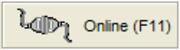
Swap the source mode of the VBOX Tools software to ‘Online’ by pressing ‘F11’ or clicking the source button in the top right of the screen. The button should display ‘Online’.
|
|
If the Disk Logging window is not already open enable the Disk Logging screen by clicking on PC File Manager in the ‘Tools’ drop-down menu. The Disk Logging window as shown right will then appear. |
.png?revision=1)
Logging Modes
Log Continuously
With ‘Log Continuously’ ticked the PC file manager will log serial data, regardless of movement.
Log Only when moving
Without ‘Log Continuously’ ticked only when the software detects movement will it log VBOX serial data directly to a file in a new folder on your computer.
At any time the disk logging can be stopped and the logged file can be opened and viewed as any other VBOX file.
Filename
The software will automatically assign the filename vblog_AAA.vbo, where AAA is a three-digit number, to new files, incrementing the number for each new file. These files are automatically stored in a folder named according to the date, which will itself be in a folder called ‘Log Files’. The ‘Log Files’ folder is created in the same folder as the VBOX Tools executable.
Even though the filename and folder are automatically assigned it is possible to change the filename to one of your own choice.
To change the file name first ensure that the disk logging is stopped. Then click the button in the filename .png?revision=1) window and enter a new file name.
window and enter a new file name.
Start logging with the new file name by clicking on the New File icon or pressing ‘F7’. .png?revision=1)
Starting and Stopping
Logging of a VBOX file to the PC’s hard disk can be started and stopped with the ‘Start’ and ‘Stop’ icons in the Disk Logging window, or the ‘F2’ and ‘F3’ keys respectively. If Logging is stopped, ‘Start’ will continue logging to the same file name. Only the ‘New File’ icon or ‘F7’ key will start logging to a new file.
Voice Tagging
|
When logging data on a PC with the File Manager tool, voice notes regarding test conditions or erroneous runs can be added to the file, which can be replayed instantly when viewing logged files in the Graph screen. To enable voice tagging, select PC File Manager from the Tools menu and check the Voice tagging enabled box. Once logging is started (by pressing F2 or clicking on the green Start button, voice tagging can then be activated and deactivated by either pressing F12, or clicking the Record button. Voice tags appear in data traces as green circles on the trace and can be replayed by clicking on these circles. |
|
.png?revision=1)
Viewing the Logged File in the Graph Screen
You can view the data that has just been logged in the main Graph screen by clicking the ‘Graph Last File’ icon or pressing ‘F5’. The Graph Screen will appear, displaying the data from the logged file. All the normal Graph functions will still be available.
.png?revision=1)
Auto Filter and Scan
The ‘Auto Filter and scan’ function is used in conjunction with the Report Generator screen. With this function enabled, when the vehicle reaches 0km/h the live data is automatically filtered, scanned and then displayed in the results table of the Report Generator screen. It is advised that this is not used without first consulting your VBOX agent.
Using the Auto Filter and Scan Facility
|
Run the Report Generator software and set up the test profile and columns as desired for your particular test. Note: The test can start and end where you like but the vehicle must come to 0km/h before the results will be processed and displayed. Enable the Disk Logging screen and tick the ‘Auto Filter and scan’ option. Now conduct your test and at the end of your test, when the vehicle reaches 0km/h, the VBOXTools software will change source mode to ‘File’ and then display the filtered and scanned results in the Report Generator window. To start the Disk Logging and Report Generator again, press ‘F11’ to swap the source back to VBOX. |
|
.png?revision=1)
Viewing the Filtered and Scanned Results
The text results of the run are shown automatically in the Report Generator grid. To view the results from a run in the graph window ensure that you include the column title ‘Graph Run’ in the Report Generator screen.
.png?revision=1)
When the run has finished click on the ‘Graph’ icon in the ‘Graph run’ column. This run will then be displayed in the Graph Window.
.png?revision=1)