05 - Calibrating the fitted TC system
Calibration and Test Procedure Methods
Once the Traction Control loom has been connected (Power, ground, RPM, injectors and wheel speed signals) the system is ready for calibration and testing. The system will need calibrating before it will work properly.
The easiest way to do this is by running the Traction Setup software on a Windows laptop and connecting to the diagnostic lead. Note most modern laptops will not have a 9 pin serial port and therefore a USB to RS232 Serial convertor is required.
Alternatively the calibration plug included with the Traction Control can be used. See the sections below for further detail on both methods.
Using the software to calibrate and test
1. Power the TC on; connect a serial cable to the diagnostic port from your Laptop or PC. Run the software. Find the assigned COM port under options – COM port and then select read settings.
.png?revision=1)
.png?revision=1)
.png?revision=1)
When successful the SW will display “Traction memory read OK”
If the user wishes to apply a change in configuration they simply need to select Write settings to apply this. Again once written successfully, the Traction Setup will display “Traction memory written OK”
See the setup software article for further details on connecting to and using the Traction Setup software.
Checking the RPM signal
Once connected to the software select Graph and then Real Time Start
.png?revision=1) |
|
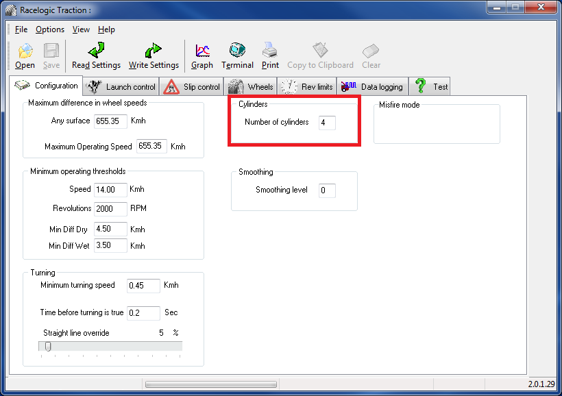
Run the engine and ensure an RPM signal is present. If the value is incorrect close the graph, navigate to Configuration – number of cylinders and change this value. For example if the RPM value is half of truth then halve the number of cylinders value, this is in fact simply a scale for the RPM so will not affect operation if it doesn’t match the cars actual number of cylinders.
Ensure you select write settings to apply any changes made.

Checking wheel speed signals
Once the RPM signal is reading the correct value, ensure all wheel speed signals are present and assigned to the correct corner.
The easiest way to do this is to again view the real time graph, jack each corner of the car up, spin the wheel by hand and note the channel number and corner of the car.
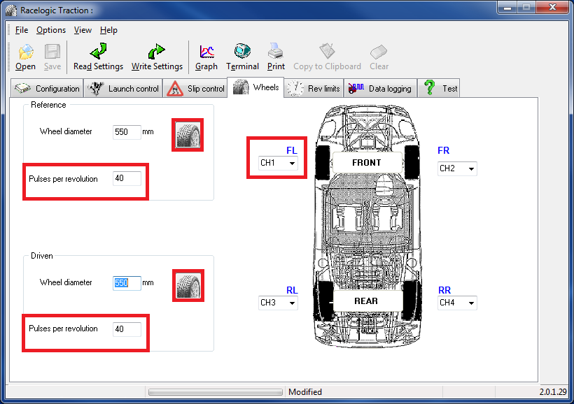
Once you have done this for all four sides exit the graph, select wheels and assign the correct channel to the correct corner.
Finally ensure the correct wheel sizes and pulses per revolution values (number of teeth on reluctor ring) are entered. Clicking the wheel icon calculates the correct diameter for a given wheel size (i.e. 195 / 45 17) automatically. Alternatively the value can be written manually.
The wheel diameters must be entered in millimeters, and must be the diameter of the tyre. This allows the system to calculate the rolling circumference.
Press the .jpg?revision=1) button and a window will appear.
button and a window will appear.
.png?revision=1)
This lets you input the values as shown on the side of your tyre.
.png?revision=1)
E.g. 205 / 45 R 16
Finally select write settings then turn the car off and on to allow the changes to take effect.

Once completed again run the real time graph function (log a file) take the car for a drive ensuring all four wheel speeds and the RPM are present and clean.
.png?revision=1)
Using the calibration plug
If a laptop is not available the traction control system is also fitted with self-diagnostics which are enabled by fitting the calibration plug (included in the kit) to the diagnostics port. This enables engine RPM and 4 wheel speeds to be indicated via an LED on the diagnostic lead. Diagnostic mode is accessed at any time by selecting the desired wheel speed channel or RPM using the rotary adjuster.
Please check the items on the checklist below are correct before calibrating the system. The checks are in normal type and the tests are in italics.
Traction Control Checklist
- Has the 12 Volts supply been connected to the Red Wire (Pin 2) of the Traction Control?
- Has the black GND wire (Pin 1) been connected to a suitable GND?
Complete checks 1 and 2 and Turn the ignition switch on.
Check if the diagnostic light illuminates for 2 seconds, the switch will light up if in the off position. - Have all the injector wires been cut and spliced into the traction control wiring loom?
Inputs to the ECU side and outputs to the fuel injector side?
Start the car and ensure it runs without misfiring. - Has the black/white RPM wire (Pin 18) been connected to a suitable 0 – 5 or 0-12 Volt signal?
Switch the adjuster to the off position. Start the car and Rev, ensuring the diagnostic light flashes in time. - Have all the ABS wires been connected to each Traction Control wheel speed input?
Select 15%, 10%, 5% and Wet on the adjuster which will indicate wheel speeds 1 through to 4 on the LED.
The light must have started flashing above 20 km/h.
If all the answers to the checklist above are yes please proceed to the next section.
Diagnostic Modes
The Diagnostic modes can only be used once the adjuster has been connected. The diagnostic functions will not operate if the ‘enable data logging’ function is enabled.
The adjuster can also be used to switch between diagnostic modes. The LED connected to the diagnostic wire acts as a diagnostic tool which can display each of the 4 wheel speeds and the engine RPM.
| Adjuster Position | Description | Traction control wire colour |
|---|---|---|
| Wet | Wheel speed 1 | Red |
| 5% | Wheel speed 2 | Blue |
| 10% | Wheel speed 3 | Yellow |
| 15% | Wheel speed 4 | Green |
| 20% | RPM | White/Black |
| Off | RPM | White/Black |
When any of the wheel speed modes are selected, the light will be constant when the car is stationary. When the car is driven, the faster the car goes the higher the frequency the led will flash.
For example, if the adjuster is set to 10% and the diagnostic light does not flash, swap the yellow wire to the other side of the ABS sensor, to see if this cures the problem.
To test if the RPM wire is connected to a valid RPM source the adjuster will need to be switched to Off or to 20%. By revving the car the frequency of the led should increase.
.png?revision=1)
Adjuster positions for traction control diagnostics
NOTE – On the TC8 with Data logging, the logging must be turned OFF for the Diagnostic mode to work. It can be turned ON once the system has been setup.
Wheel Speed Calibration
Before the Traction Control system will work the wheel speeds have to be configured to tell the system which are driven and which are reference wheels. To configure the wheel speeds follow the procedure below.
Start the car. Take the car to a section of road with a short straight followed by a slow 180 degree corner, left or right.
.png?revision=1)
Calibration Procedure
- Drive the car to a suitable test road, preferably where almost full lock can be used.
- Switch the engine off and wait for the system to power down (If in doubt turn the adjuster to the off position and wait for the light to go off).
- Plug the calibration adapter into the diagnostic lead.
- Turn the ignition switch to the on position.
- After 2-10 seconds the LED will start flashing (Once every second) to indicate the system is in calibration mode.
- Start the car.
- Drive the car towards the corner, and turn the corner
- Once the system is calibrated the light will stop flashing once a second and will flash in time with RPM or any of the four wheel speeds, depending upon the switch position.
Final Test
Jack the driven wheels of the car and start the engine. Engage a gear and spin the wheels. When the wheels are spun above 14 km/h does the engine misfire?
Yes - The system is working correctly and the fitting procedure is finished.
No - Check that the RPM source has been connected and is being supplied by a valid signal by repeating section 5.3.
.jpg?revision=1)

.png?revision=1)