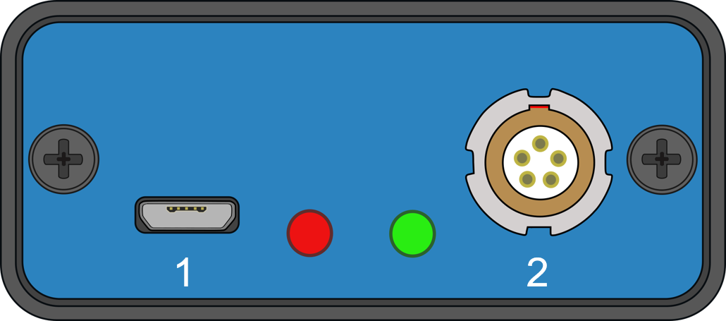
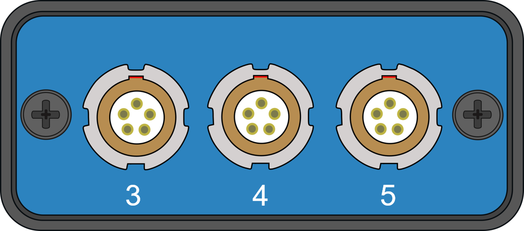
CAN Gateway - PIN OUTS

|
Front view of CAN Gateway |
Rear view of CAN Gateway |
Connector 1 - USB (USB Micro-B)
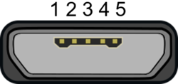
| PIN | I/O | Function |
|---|---|---|
| 1 | I | Power |
| 2 | I | Data - |
| 3 | I/O | Data + |
| 4 | I/O | ID |
| 5 | I/O | Ground |
| Chassis | I | Ground |
Connector 2 - Vehicle (Lemo 5 PIN)
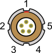
| PIN | I/O | Function |
|---|---|---|
| 1 | O | RS232-2 Rx (1) |
| 2 | I | RS232-2 Tx (1) |
| 3 | I/O | CAN High (CAN A) |
| 4 | I/O | CAN Low (CAN A) |
| 5 | O | Power |
Connector 3 - VBOX (Lemo 5 PIN)

| PIN | I/O | Function |
|---|---|---|
| 1 | O | RS232 Rx |
| 2 | I | RS232 Tx |
| 3 | I/O | CAN High (CAN B) |
| 4 | I/O | CAN Low (CAN B) |
| 5 | O | Power |
Connector 4 - OLED (Lemo 5 PIN)

| PIN | I/O | Function |
|---|---|---|
| 1 | O | RS232 Rx (pass-through) |
| 2 | I | RS232 Tx (pass-through) |
| 3 | I/O | CAN High (CAN B) |
| 4 | I/O | CAN Low (CAN B) |
| 5 | O | Power |
Connector 5 - Module (Lemo 5 PIN)

| PIN | I/O | Function |
|---|---|---|
| 1 | O | RS232 Rx (2) |
| 2 | I | RS232 Tx (2) |
| 3 | I/O | CAN High (CAN B) |
| 4 | I/O | CAN Low (CAN B) |
| 5 | O | Power |

