02 - VIPS Hardware Installation
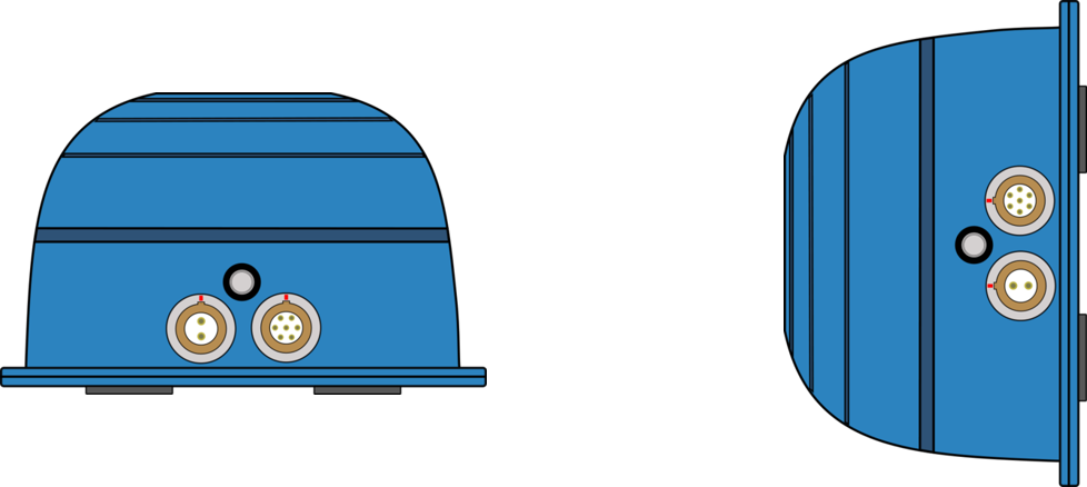
Beacon (VIPS-B-V1) Installation
When first considering a VIPS installation or demonstration, it is important to understand the shape and size of the test area and thus the minimum number of beacons that will be required.
VIPS will need at least 6 beacons in view at any one time to compute a solution. For a simple installation, Racelogic recommend placing the beacons in a ‘Square’ formation with spacing between the beacons of around 25–30 m, as below.
![]()
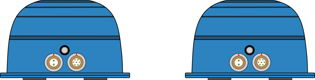
The beacons require a 9 – 36 V power source that is connected to the 2 way Lemo connector. The other Lemo connector on the beacon is for Firmware upgrades and should be covered with the supplied splashproof plug to ensure waterproofness.
The VIPS beacons have 4 magnets on the base allowing for easy installation onto any ferrous surface, however Racelogic can supply metallic plates that can attach to a tripod for quick installations.
Beacon Installation Considerations
When mounting the VIPS beacons, there are considerations that should be made.
- If operating in an outdoor/indoor mode, then the rover will not switch to use the VIPS until 6 beacons are in view. This means that it is only the first 6 beacons that will need to be placed closer together to ensure that 6 beacons are in view before the vehicle enters the test area. The remaining beacons can be placed with a greater separation so long as the vehicle is always within a 60 m radius of at least 6 beacons.
- For greater accuracy, it is recommended that the beacons are placed between 3–5 m above ground (i.e. above the roof of the test vehicle) and that each beacon varies in height by at least 300 mm to the nearest beacons, alternating in a high-low pattern.
- It is important when mounting the beacons that they are not mounted within at least 200 mm (or greater if possible) of an object, other than the surface the beacon is mounted to, that could cause reflections (e.g. a wall or metal structure) and that the beacons are mounted in the correct orientation in relation to the expected orientation of the Rover when in use.
- The beacons can be mounted pointing up or pointing down, but remember to set the orientation in the Survey Software.
- The majority of the beacons should be as high up as possible, however the area directly underneath the beacon (in a small cone) gives poor reception if the prism and metal disc are retained.
- Some of the beacons (4 is a good number) should be at a lower level so that there is good variation in geometry. Opposite to what you might think, It is much better to put the beacons as far away from the receiver as possible, than getting them in close.
- The beacons should be turned so that the connectors on the beacon point towards the Robotic Total Station. This is because the prisms are fitted so that they are aligned in the direction of the connectors, and it will give you the best accuracy during the survey.
- Make sure you can clearly see all of the Prisms from the location of the Total Station. Try not to have two prisms in line with each other from the view of the Total Station as it will be difficult to select the correct one.
- Bear in mind that the Total Station has a maximum upwards looking angle of 55°, so it won’t see a prism above this elevation from the horizontal.
- Beacons can be mounted on metal and the feet are magnetic for this purpose, however the body of the beacon should be kept at least 30 cm from any metal which is above the base. For example, the beacon in the image below is in a bad location, to improve it, use something like a Smallrig extender arm to move it 30 cm from the metal. The reason is that the metal will absorb and reflect some of the UWB signal, causing large inaccuracies and a reduced range.
![]()
-
To receive the best accuracies of position and angles, the maximum number of beacons available to a solution (12) should be utilised within line of sight to the receiver.
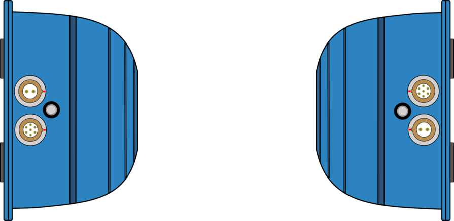
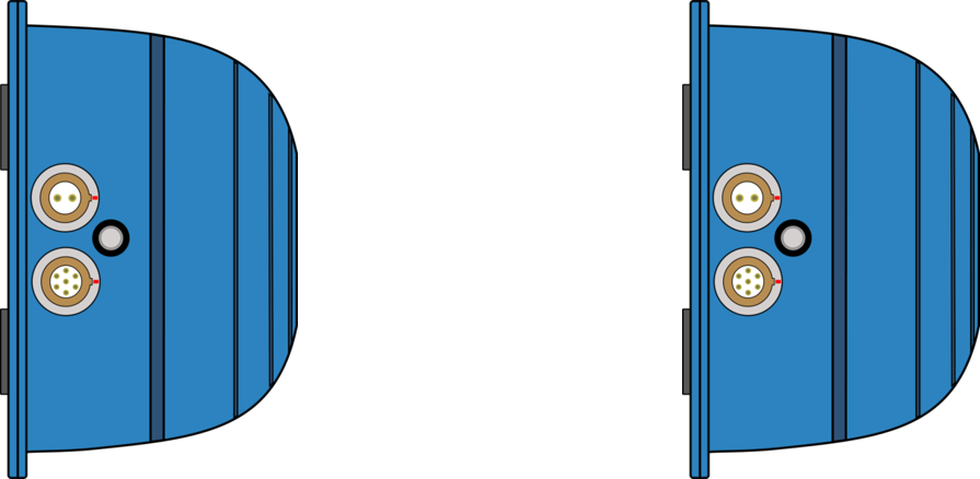
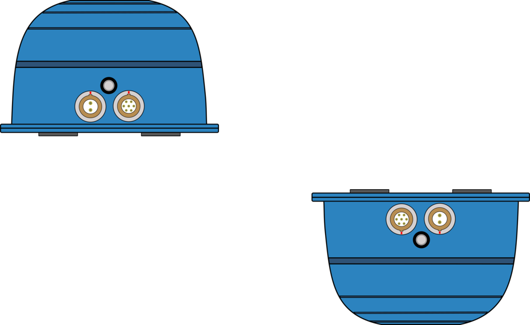
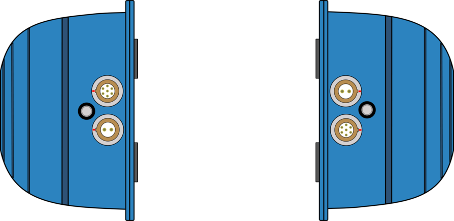
Suitable Beacon Orientations
|
✔ |
 |
Side by side |
| ✔ |  |
Side by side with small height difference |
| ✔ |  |
Side by side with large height difference, tops towards each other |
| ✗ |  |
Side by side with large height difference |
| ✗ |  |
Tops together |
| ✗ |  |
Tops to base |
| ✗ |  |
Base to base |
| ✗ |  |
Side to base |
| ✗ |  |
Side by side with large height difference, tops away from each other |
Rover (VIPS-R-V2) Installation
- The VIPS Rover looks similar to the Beacon, however the rover contains an internal IMU and so care should be taken to ensure that the Rover is mounted to an area that has the least vibration. If being installed on a vehicle, this is usually towards the rear, just in front of the rear windshield.
- The rover should be mounted in a way such that it has a clear view to the beacons and away from any objects that may block that view (roof bars, radio antennas, etc).
- Make sure there is no metal close to the receiver, even a metal clamp close to the bottom of the receiver, or a monitor in the line of sight to beacons can cause significant issues.