LabSat Antenna Matrix
The choice of antenna for recording and replaying scenarios during testing is crucial to the accuracy and relevance of the tests.
LabSat record and replay simulation systems are supplied with magnetic active ‘patch’ antennas. These antennas are active and are not suitable for rebroadcasting to a receiver with an internal antenna.
Most countries have regulations regarding the retransmission of signals, and you must be aware of the local rules that apply to your testing system.
Racelogic has a small selection of rebroadcast antennas available. These must be used in an RF-screened environment.
To assist with testing of internal antenna devices, Racelogic also supply a LabSat GNSS Test Enclosure for use with devices that have internal antennas, such as Smartphones and Satellite navigation devices.
When recording GNSS signals with LabSat systems, the antenna must have a suitable ground plane, such as a car roof. We always advise using the antenna from the application or device you are testing. If the antenna is a passive antenna, placed next to the receiver in the device, you may need to use an LNA to boost the power and cover the signal loss of the cable connected to the device under test (DUT).
Click on an antenna below to view its technical specifications.
Antenna Overview
| RLACS354 | |
|
|
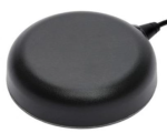
Extended Filter Triple Band GNSS Antenna + L Band An active antenna suitable for recording GPS L1/L2/L5, GLONASS G1/G2/G3, BeiDou B1/B2/B2a, Galileo E1/E5a+b, IRNSS/NavIC L5 and L-band corrections signals.
Supplied with LabSat 4. |
| RLACS249 | |
|
|
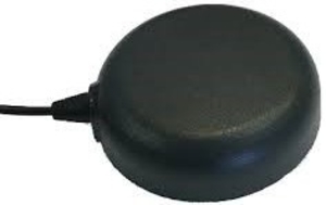
Active Triple Band GNSS Antenna An active antenna suitable for recording GPS L1/L2/L5, GLONASS G1/G2/G3, BeiDou B1/B2, Galileo E1/E5a+b and L-band corrections signals.
Supplied with LabSat 3 Wideband. |
.jpg?revision=1)
| RLACS198 | |
.jpg?revision=1) |
Active Quad Constellation Antenna An active antenna suitable for recording GPS/GLONASS/BeiDou/Galileo signals.
Supplied with LabSat 3. |
| RLACS156 | |
.jpg?revision=1) |
Active GPS + GLONASS Antenna An active antenna suitable for recording GPS/GLONASS/Galileo L1 signals.
Supplied with LabSat 2. |
| RLACS206 | |
.jpg?revision=1) |
Passive GPS/GLONASS Antenna A passive antenna suitable for recording/replaying GPS/GLONASS/Galileo L1 signals.
Optional Accessory. |
| RLACS205 | |
.jpg?revision=1) |
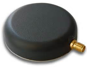
Active GPS Antenna An active right-angle antenna suitable for recording GPS L1 signals only.
Optional Accessory. |
| RLACS219 | |
.jpg?revision=1) |
Passive GPS/GLONASS/BeiDou Antenna A passive antenna suitable for recording/replaying GPS/Galileo/GLONASS/BDS L1 signals.
Optional Accessory. |
| RLACS278 | |
 |
Passive Triple Band GNSS Antenna A passive antenna suitable for replaying GPS L1/L2/L5, GLONASS G1/G2/G3, BeiDou B1/B2, Galileo E1/E5a+b and L-band corrections signals
Optional Accessory. |
| RLACS225 | |
.jpg?revision=1) |
LabSat GNSS Test Enclosure RF-shielded enclosure suitable for testing GNSS devices with internal antennas.
RLACS219 included. |