19 - LabSat 2 PIN OUTS

Front View of LabSat 2
Connector 1 - POWER (Lemo 2 PIN)

| PIN | I/O | Function | Range |
|---|---|---|---|
| 1 | I | Power+ | 5.4 V to 30 V |
| 2 | I | Ground | 0V |
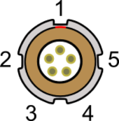
Connector 2 - AUX (Lemo 5 PIN)

| PIN | I/O | Function | Range |
|---|---|---|---|
| 1 | O | Module Direction Control | ±12 V |
| 2 | I | Reserved | ±12 V |
| 3 | I | Digital Input 1 (DIG IN) | 0 V to 5 V |
| 4 | O | Digital Output 1 | 0 V to 5 V |
| 5 | O | +V Power | Same as Power+ |
SMA Connectors - RF OUT, RF IN and CLOCK IN

| PIN | Name | Function | Range |
|---|---|---|---|
| Center | RF IN |
RF Signal including 3 V DC bias for active antenna |
|
| RF OUT | RF Signal Output DC Blocked | ||
| CLOCK IN | 10 MHz Reference clock. Must be enabled in LabSat software | 10.000 MHz +6 dB | |
| Chassis | - | Ground |
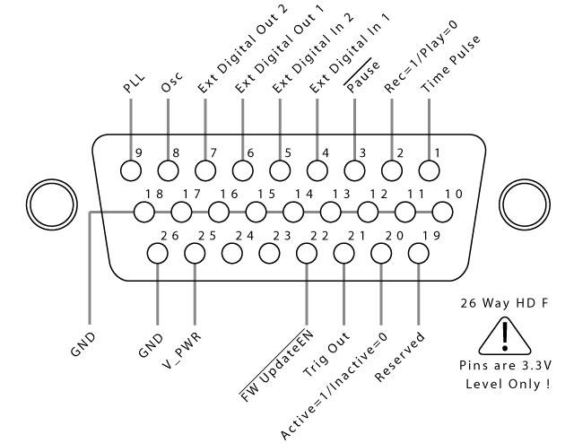
26 way D type connector

The functionality available from the 26 Way D-Type connector on the front panel of LabSat 2, is described in the table below.
| Number | Name | I/O | Function |
|---|---|---|---|
| 1 | DIO 0 | O | 1-PPS (From Internal GPS when locked to rec/play signal) |
| 2 | DIO 1 | O | Rec/Play (Rec=1,Play=0) |
| 3 | DIO 2 | I | Pause. Ground to Pause Rec/Rep |
| 4 | DIO 3 | I | Extended Digital Input 1 (Replaces Second RF Channel) |
| 5 | DIO 4 | I | Extended Digital Input 2 (Replaces Second RF Channel) |
| 6 | DIO 5 | O | Extended Digital Output 1 (Replaces Second RF Channel) |
| 7 | DIO 6 | O | Extended Digital Output 2 (Replaces Second RF Channel) |
| 8 | DIO 7 | O | 16.368 MHz Clock Signal (Direct from Osc) |
| 9 | DIO 8 | O | 16.368 MHz Reference signal output (must be enabled in software) |
| 10 ~ 18 | GND | Signal Ground | |
| 19 | DIO 9 | O | Reserved for factory test |
| 20 | DIO 10 | O | Record/Replay activity output. 0=Inactive / 1=Recording Active |
| 21 | DIO 11 | O | Trigger Output (Recorded Trigger Output during replay or pass-through of Trig In during record) |
| 22 | Update | I | Connect to pin 14(GND) to Enable firmware update mode on power-on |
| 23 | - | - | Not used |
| 24 | - | - | Not used |
| 25 | V_PWR | O | Connected to PWR input (max 200 mA) |
| 26 | GND | O |
Caution!
The Digital I/O connector uses 3.3 Volt logic levels. Connection of any of the IO signals to levels above 3.3 Volts will cause permanent damage to the internal logic.
