04 - SatGen Dynamic Scenario Creation
Draw Route
To create a dynamic route click the draw route button. The new window allows you to draw a route on the map quickly and accurately.
By inserting a location description in the search box, you can find any location in Google maps. You can then easily insert a route by clicking on the map in sequence. You can zoom in or out on the map for additional accuracy using the normal Google map commands. You can select digital maps, terrain maps or satellite photo maps and can edit or clear the route by clicking the relevant command.

Draw the required route by clicking in sequence to draw the route on the Google map. You can save the route as a KML file. When you click the OK button, the drawn route is automatically inserted into the software and is ready for processing into a scenario.
The software will show the drawn route in the Scenario details screen with a display of the position (x,y) in meters and the speed profile in km/h against time.
Scenario Settings
In the Scenario settings section you can select the more tick box to reveal further settings. It is easy to define date and time (UTC). The selected dynamics will be reflected in the Scenario Details screen.
High Dynamics will have a maximum speed of 300 km/h, Medium Dynamics has a maximum of 100 km/h, Low Dynamics has a maximum of 60 km/h and in User Dynamics the maximum speed can be dictated by the user. The software will automatically smooth the dynamic data to reflect turns at slower speeds.
You can define the update rate for the route from 1 Hz to 100 Hz. This will define the granularity of the route created in the software.
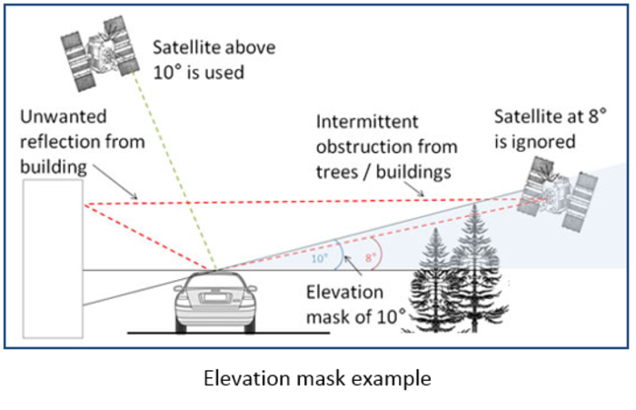
You can set the elevation mask to replicate the antenna environment when you are using a GPS receiver. This feature is normally used to improve GPS signal quality when nearby obstacles like trees and building are reflecting or temporarily obscuring the signal from satellites at low elevation. Raising the mask will cause a GPS engine to ignore satellites below the mask angle, and must be used carefully as it also reduces the total number of received satellites. The higher the elevation mask the fewer satellites you will have in the created scenario file. The elevation mask would normally be set to 5 degrees.
Select the almanac update to automatic or manual. For automatic almanac download the software needs to be connected via the PC to the internet to download the relevant almanac required.
Note: BeiDou almanac BDS_20140912_FakeAllSats.alm includes all future and current satellites to replicate the full future system for worldwide testing.
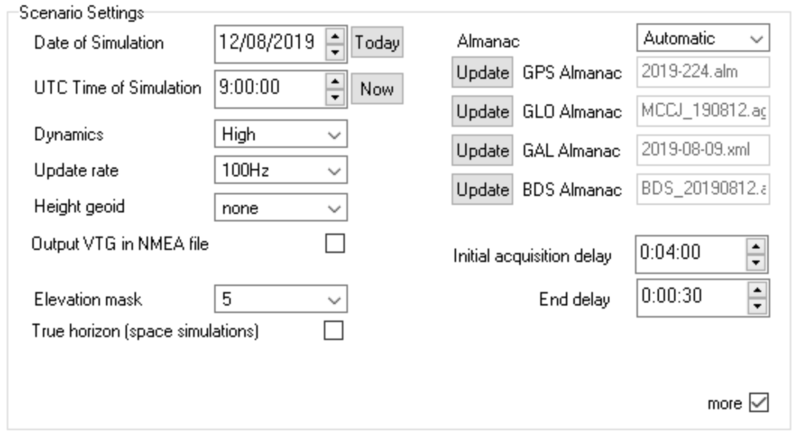
Scenario settings section
These almanacs are stored in the folder 'Almanacs' located in My Documents\SatGen\Almanacs. The initial acquisition delay should be set to reflect the static time allowed for the device under test (DUT) to acquire the signals and to start to navigate. As a standard Racelogic recommend 4 minutes to allow for DUT set up and signal acquisition. End delay should be set to allow for the receiver to stop and any files saved of the DUT performance. Normally set to 30 seconds.
True Horizon
During the simulation the elevation mask changes dynamically to follow the true horizon visible from each individual point of the trajectory. This is especially useful for space simulations when the horizon is very low and the number of visible satellites is higher than on the ground. For example, the horizon visible from the International Space Station is at around -20°.
User Dynamics Input
The dynamics setting allows for four dynamic settings; Low, Medium, High, settings and a user controlled input screen.
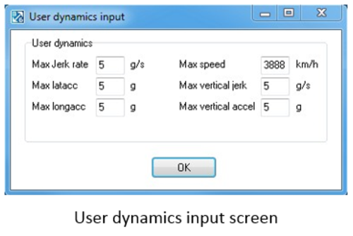
- Max jerk rate: This controls the maximum rate of change of acceleration in a 2D horizontal plane, a low setting would allow for slowly increasing acceleration and a high setting giving a rapid change.
- Max lat acc: The maximum lateral acceleration controls the maximum acceleration perpendicular to the direction of travel.
- Max long acc: The maximum longitudinal acceleration controls the maximum acceleration/deceleration in the direction of travel.
- Max speed: The maximum speed controls the maximum speed the scenario can achieve.
- Max vertical jerk: The Maximum vertical jerk rate controls the rate of change of acceleration in the vertical direction.
- Max vertical accel: The maximum acceleration controls the acceleration in the vertical direction.
SatGen V3 Height
When establishing a position solution, a GPS receiver generally works in Earth Centred Earth Fixed (ECEF) coordinates. It then translates these using a given datum into geodetic coordinates - latitude, longitude, altitude. The datum specifies an oblate spheroid model for the earth that best approximates the surface of the planet, ignoring all topographical irregularities; different datum’s can be chosen to best approximate the region of interest to the end user. SatGen v3 uses the de facto standard World Geodetic System (WGS 84) which is applicable globally.
The initial altitude determined by translating the ECEF X,Y,Z to geodetic latitude, longitude altitude with the WGS 84 datum is an altitude above (or below) the theoretical oblate spheroid and not the surface of the planet in reality. To derive a more accurate representation of the true altitude, a GPS receiver will then use a model of the earth's gravitational field to reference the altitude to mean sea level (MSL). Various models exist for these estimates of MSL around the world, using increasing numbers of coefficients to derive more accurate estimates. The most common are EGM 84, EGM 96 and EGM 2008. Any altitude you enter into SatGen will be taken as height above MSL and in the process of simulation, this height will be added to the geoid separation for the current latitude and longitude, as estimated by the EGM84 geoid model. When generating a simulation from a provided NMEA file containing $GGA sentences, SatGen does not perform any geoid modelling, but instead uses the geoid separation in addition to the altitude above MSL provided in the NMEA 0183 GGA sentence.
Carrier to Noise Ratio
SatGen can reduce the signal to noise ratio by adding some artificial noise to the data. The carrier-to-noise-density ratio C/N0 is expressed as attenuation from the pure signal level. C/N0 can now be reduced by up to 15 dB-Hz in 1 dB-Hz steps. If attenuation is zero, pure signal is generated, otherwise the same amount of artificial noise is added to all simulated signals.
Note: The attenuation is not calibrated, users should not assume that a 6 dB change in attenuation will adjust the effective C/N0 by exactly 6 dB-Hz.
We recommend generating pure signal (software attenuation disabled (0)). Some GNSS receivers may require a lower signal level to acquire the signal and get a lock. When using LabSat 3 or LabSat 3 Wideband, the output signal level can be reduced by using the up and down buttons on the unit. If using LabSat or LabSat 2, hardware signal attenuators connected to the RF output are recommended. Different receivers can accept different signal levels, some of them may require as much as -30 dB or even -40 dB attenuation. Experimentation may be needed. Software attenuation within SatGen should only be used if hardware attenuation is unavailable.
Noise functionality is disabled on LabSat 3 Wideband scenarios if more than 3 frequency bands are in use. Pure signal is then generated.