GNSS Antenna Placement and Setup
GNSS Antenna Placement
|
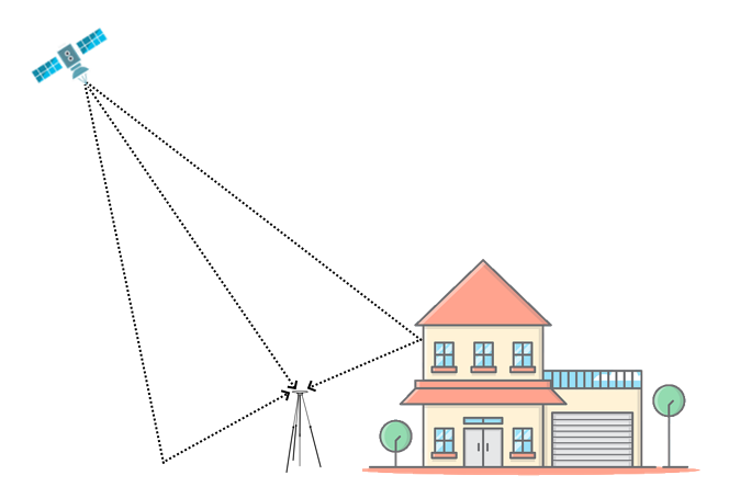
Appropriate placement of the GNSS antenna is crucial to the quality of the data that is being recorded. Be aware of objects that can shadow the antenna or block the signal to the antenna. Some objects can also reflect signals which can send weaker GNSS signals to the antenna. This is called multipath, and these reflections can disturb the signal in an unpredictable way. If an antenna is not mounted on a large enough ground plane, multipath reflections can also come from the ground beneath the antenna. If you are using the antenna without a sufficient ground plane (such as on a bike or carrying the unit by hand), you can put a sheet of metal underneath the antenna (this can for example be copper or aluminium foil) or use an antenna with strong multipath-rejection properties (ACS320). Antennas, such as the ACS320, are much larger and more expensive than the standard antennas that come supplied with a VBOX unit, but you can mount them on a pole to get them higher from the ground and away from shadowing items. On a motorbike, you should place the antenna as far from the rider as possible to reduce the rider's shadowing effect. The best place is usually at the back of the bike. |
Illustration showing multipath reflections from the ground and surrounding buildings. |
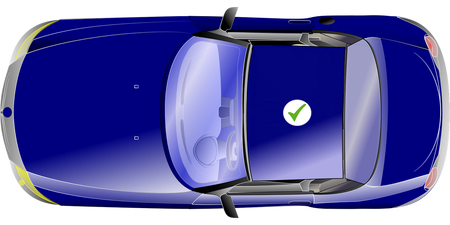
When you are placing the GNSS antenna on a vehicle:
Do:
Use the GNSS antenna in the centre of a metal roof or on a metal ground plane that has a radius of at least 5 cm.
Make sure that the GNSS antenna is placed away from anything than can cause blockages or multi-path, such as roof bars or radio antennas.
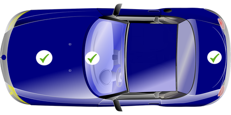
Do not:
Mount the antenna close to the edge of the roof as reflections from the ground may interfere with the signals.
|
Illustration of the recommended GNSS antenna placement location on a vehicle. |
Illustration of alternative GNSS antenna placement locations on a vehicle. |
|
|
For non-magnetic surfaces:
If the vehicle does not have a metal roof you can:
|
Use copper or aluminium foil to create a shaped ground plane that is at least 10 cm in diameter and place it underneath the antenna.
|
|
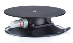
Use a Suction Roof Mount with Steel Plate (RLACS334). |
RLACS334 |
Dual Antenna Systems
When using dual antennas, the antenna separation affects the accuracy of the dual antenna-derived data channels. You will experience greater accuracy the further apart they are. However, on a vehicle it is most common to have a separation distance of between 0.5 m to 2.5 m. You can see the accuracy differences in the overview below.
| Slip Angle Accuracy | Pitch/Roll Angle Accuracy | ||
|---|---|---|---|
| <0.2° rms at 0.5 m antenna separation <0.1° rms at 1.0 m antenna separation <0.067° rms at 1.5 m antenna separation <0.05° rms at 2.0 m antenna separation <0.04° rms at 2.5 m antenna separation |
<0.14° rms at 0.5 m antenna separation <0.07° rms at 1.0 m antenna separation <0.047° rms at 1.5 m antenna separation <0.035° rms at 2.0 m antenna separation <0.028° rms at 2.5 m antenna separation |
|
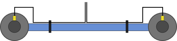
IMPORTANT Timing is a very important aspect of the dual antenna lock and identical cable lengths will ensure that signal propagation delays do not cause unreliable dual lock. |
You can use a Dual Antenna Mounting Pole (RLACS171) to increase the separation further.
 |
 |
Dual Antenna Mounting
Note: It is important that you keep the GNSS antenna cables separated when you are installing the equipment on and in the car. Do not bundle or tape them together as this can cause cross-talk and affect your data.
Click on the blue heading for the mounting system you want to use. With Dual Antenna Mounting Pole
Without Dual Antenna Mounting PoleWhen mounting the antennas directly to the vehicle roof, ensure that the antenna placement still follows the guidance of the single antenna above (i.e. clear ground-plane, away from obstruction). |
|||||

|
Do: |
|
|
Do not: |
Reflections from the ground may interfere with the signals. |
_PITCH.png?revision=1) |
_ROLL.png?revision=1) |
| Pitch Mode | Roll Mode |
Antenna Separation Measurement
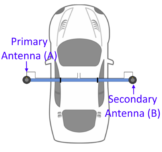
The most important factor for dual antenna testing is the correct configuration of the separation distance between the centre points of the two antennas. This allows the VBOX unit to acquire and maintain dual antenna lock. The physical separation distance between the two antennas should be measured as accurately as possible, and entered in to the Antenna Separation setting in the Dual Antenna menu in VBOX Setup.
To make sure that the reference is consistent, the two antennas should be aligned with the gold antenna connectors pointing in the same direction. This makes it eaier to make a physical connector-to-connector reference measurement.
The antennas should be placed on a level plane if possible.
Measure the separation distance between the primary and the secondary antenna.
We recommend you measure the separation from the outer edge of antenna connector A to the outer edge of antenna connector B.
The measured distance between the antennas should be the 2D distance as viewed from above. It is not the straight-line distance between the antennas regardless of the mounting angle.
Notes:
- It is essential for dual-antenna operation that you enter the antenna separation accurately.
- If you are using a VBOX 3i ADAS, the antenna separation will be calculated automatically.
Roll Mode
In Dual Antenna Mode, you can often test the roll and pitch measurements separately. If you wish to set up you antennas across the width of the car to measure the roll angle, you must make sure that you enable Roll Mode in the Dual Antenna menu in VBOX Setup.
Slip Offsets
In Dual Antenna mode, you sometimes need to take slip measurements from other locations on the vehicle, for example the centre of gravity or slip over the wheels. You can configure this in the Slip offsets section in the Dual Antenna menu in VBOX Setup. You can set additional locations by entering the offset distances from the primary antenna location in the Ahead/Behind and Left/Right settings.
When using an external IMU: When an IMU module is connected to the VBOX unit, the yaw rate channel will be used in the calculated slip channels, as the signal to noise ratio is much lower than the GPS derived yaw rate. This reduces noise in the slip translation process.
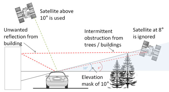
Satellite Elevation Mask
You can use the Satellite Elevation Mask feature to improve the GNSS signal quality when nearby obstacles, such as trees and buildings, are reflecting or temporarily obscuring the signal from satellites at low elevation. Raising the mask will make the GNSS engine in your VBOX unit ignore signals from satellites that are located below the mask angle. As this feature will reduce the total number of satellites it receives a signal from, you must use it carefully to make sure that you have sufficient satellites for your test.
You can change the elevation mask angle in VBOX Setup or with VBOX Manager.