Channel Name Definitions - Sign Posts
| Channel Name | Description | Unit |
|---|---|---|
| ID1 |
The ID number of the Sign post that is currently being referenced by all channels suffixed by "1" (I.e. Range1, TTC1 etc). When a new sign post comes into the detection range it will always be assigned the lowest available ID slot. |
|
| Range1 |
The direct distance between the sign post in ID1 and the Sensor Offset location.
|
m |
| Lat_Range1 |
The Lateral distance between the sign post in ID1 and the Sensor Offset location measured perpendicularly to the Subject Vehicle's Heading. The heading source used will be the "Robot_Head" when in Dual antenna mode or when IMU integration is enabled, otherwise it will use the position derived heading when in Single antenna only.
|
m |
| Lng_range1 |
The Longitudinal distance between the sign post in ID1 and the Sensor Offset location measured in the direction of the Subject Vehicle's Heading. The heading source used will be the "Robot_Head" when in Dual antenna mode or when IMU integration is enabled, otherwise it will use the position derived heading when in Single antenna only.
|
m |
| TTC1 |
The time required to cross the Sign post in ID1 , based on the subject vehicles heading and current speed. The heading source used will be the "Robot_Head" when in Dual antenna mode or when IMU integration is enabled, otherwise it will use the position derived heading when in Single antenna only. |
s |
| Angle1 |
The Angle between the Sign Post in ID1 and the Sensor offset location.
|
° |
| ID2 |
The ID number of the Sign post that is currently being referenced by all channels suffixed by "2" (I.e. Range2, TTC2 etc). When a new sign post comes into the detection range it will always be assigned the lowest available ID slot. |
|
| Range2 |
The direct distance between the sign post in ID2 and the Sensor offset location.
|
m |
| Lat_Range2 |
The Lateral distance between the sign post in ID2 and the Sensor Offset location measured perpendicularly to the Subject Vehicle's Heading. The heading source used will be the "Robot_Head" when in Dual antenna mode or when IMU integration is enabled, otherwise it will use the position derived heading when in Single antenna only.
|
m |
| Lng_range2 |
The The heading source used will be the "Robot_Head" when in Dual antenna mode or when IMU integration is enabled, otherwise it will use the position derived heading when in Single antenna only.
|
m |
| TTC2 |
The time required to cross the Sign post in ID2 , based on the subject vehicles heading and current speed. The heading source used will be the "Robot_Head" when in Dual antenna mode or when IMU integration is enabled, otherwise it will use the position derived heading when in Single antenna only. |
s |
| Angle2 |
The Angle between the Sign Post in ID2 and the Sensor offset location.
|
° |
| ID3 |
The ID number of the Sign post that is currently being referenced by all channels suffixed by "3" (I.e. Range3, TTC3 etc). When a new sign post comes into the detection range it will always be assigned the lowest available ID slot. |
|
| Range3 |
The direct distance between the sign post in ID3 and the Sensor offset location.
|
m |
| Lat_Range3 |
The Lateral distance between the sign post in ID3 and the Sensor Offset location measured perpendicularly to the Subject Vehicle's Heading. The heading source used will be the "Robot_Head" when in Dual antenna mode or when IMU integration is enabled, otherwise it will use the position derived heading when in Single antenna only.
|
m |
| Lng_range3 |
The heading source used will be the "Robot_Head" when in Dual antenna mode or when IMU integration is enabled, otherwise it will use the position derived heading when in Single antenna.
|
m |
| TTC3 |
The time required to cross the Sign post in ID3 , based on the subject vehicles heading and current speed. The heading source used will be the "Robot_Head" when in Dual antenna mode or when IMU integration is enabled, otherwise it will use the position derived heading when in Single antenna only. |
s |
| Angle3 |
The Angle between the Sign Post in ID3 and the Sensor offset location.
|
° |
| ID4 |
The ID number of the Sign post that is currently being referenced by all channels suffixed by "4" (I.e. Range4, TTC4 etc). When a new sign post comes into the detection range it will always be assigned the lowest available ID slot. |
|
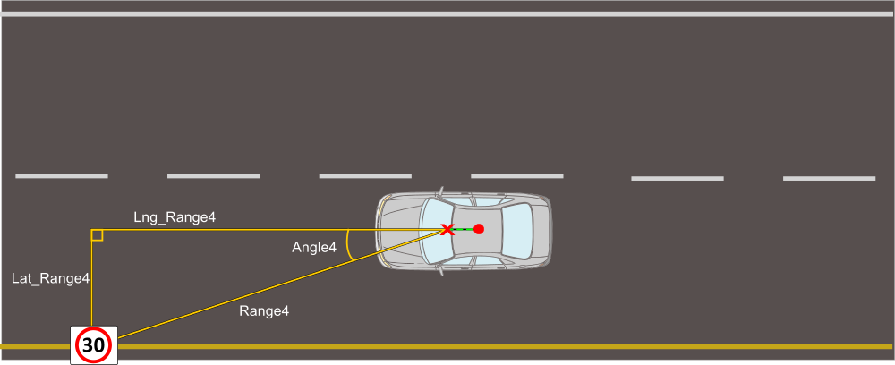
| Range4 |
The direct distance between the sign post in ID4 and the Sensor offset location.
|
m |
| Lat_Range4 |
The Lateral distance between the sign post in ID4 and the Sensor Offset location measured perpendicularly to the Subject Vehicle's Heading. The heading source used will be the "Robot_Head" when in Dual antenna mode or when IMU integration is enabled, otherwise it will use the position derived heading when in Single antenna only.
|
m |
| Lng_range4 |
The heading source used will be the "Robot_Head" when in Dual antenna mode or when IMU integration is enabled, otherwise it will use the position derived heading when in Single antenna only.
|
m |
| TTC4 |
The time required to cross the Sign post in ID4 , based on the subject vehicles heading and current speed. The heading source used will be the "Robot_Head" when in Dual antenna mode or when IMU integration is enabled, otherwise it will use the position derived heading when in Single antenna only. |
s |
| Angle4 |
The Angle between the Sign Post in ID4 and the Sensor offset location.
|
° |
| ID5 |
The ID number of the Sign post that is currently being referenced by all channels suffixed by "5" (I.e. Range5, TTC5 etc). When a new sign post comes into the detection range it will always be assigned the lowest available ID slot. |
|
| Range5 |
The direct distance between the sign post in ID5 and the Sensor offset location.
|
m |
| Lat_Range5 |
The Lateral distance between the sign post in ID5 and the Sensor Offset location measured perpendicularly to the Subject Vehicle's Heading. The heading source used will be the "Robot_Head" when in Dual antenna mode or when IMU integration is enabled, otherwise it will use the position derived heading when in Single antenna only.
|
m |
| Lng_range5 |
The heading source used will be the "Robot_Head" when in Dual antenna mode or when IMU integration is enabled, otherwise it will use the position derived heading when in Single antenna only.
|
m |
| TTC5 |
The time required to cross the Sign post in ID5 , based on the subject vehicles heading and current speed. The heading source used will be the "Robot_Head" when in Dual antenna mode or when IMU integration is enabled, otherwise it will use the position derived heading when in Single antenna only. |
s |
| Angle5 |
The Angle between the Sign Post in ID5 and the Sensor offset location.
|
° |