03 - ADC Software Overview

Settings
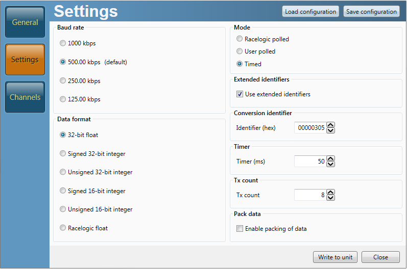
CAN Modes
Racelogic Polled
This mode should be set if the module is to be used with a Racelogic VBOX. All the CAN parameters are set to work with the Racelogic VBOX CAN protocol. In this mode no other parameters need be set or indeed will have any effect.
User Polled
This mode allows a customer’s own datalogging system to poll the module for data using the CAN bus. In this way, the output timing of the sensor can be synchronised with other CAN information. The following parameters are all used and so must be set:
Baud rate (Selectable from 125kbit/s, 250kbit/s, 500kbit/s or 1Mbit/s)
Extended Identifiers (OFF or ON)
Request identifiers (Identifiers used to request data from the sensor)
Response identifiers (Identifiers used to transmit data from the sensor)
The timer parameter has no effect in this mode.
Timed
In this mode the module will send CAN data at intervals determined by the Timer value. The following parameters are all used and so must be set:
Timer (Time interval in milliseconds between output data)
Baud rate (Selectable from 125kbit/s, 250kbit/s, 500kbit/s or 1Mbit/s)
Extended Identifiers (OFF or ON)
Response identifiers (Identifiers used to transmit data from the sensor)
The Request Identifiers have no effect in this mode.
Data Format in User Polled and Timed CAN Mode
The signal data is sent using industry standard 32bit floating point format unless specified.
Baud Rate
Baud Rate sets the bit rate of the CAN message transmission. Selectable baud rate options are:
- 1000 kbit/s
- 500 kbit/s(default)
- 250 kbit/s
- 125 kbit/s
Tx Count
This TX count is the number of CAN channels transmitted so for the 8 channel ADC03 this should be set to 8.
Timer
The timer value is in milliseconds (ms). A smaller value means data will be sent more frequently, a larger value means data will be sent less frequently. The range of values that can be entered is 0 to 65535 however the minimum value that should be entered is 10. Below this value data values may be repeated on successive cycles. If a value of 0 is entered the module will change it to 1 on the next power cycle.
Frequency output can be calculated as follows:
Freq = (1/Timer) * 1000
The Timer value for a required frequency can be calculated as follows:
Timer = (1/Freq) * 1000
Some example Timer values are shown against the frequency output.
| Timer Value [ms] | Frequency [Hz] |
|---|---|
| 10 | 100 |
| 50 | 20 |
| 100 | 10 |
| 400 | 2.5 |
| 1000 | 1 |
Extended Identifiers
Extended Identifiers can be set either ON or OFF. If they are off the CAN identifier type will be standard (11 bit). If they are on the CAN identifier type will be extended (29 bit). The Standard Identifier type allows 2048 different CAN message identifiers or message “names”. The Extended Identifier type allows 436207616 different CAN message identifiers. The identifier type should be set to match the CAN data logging equipment that the module is connected to.
Entering a value of “off”, “OFF” or “0” will turn Extended Identifiers off. Any non-zero value, “on” or “ON” will turn Extended Identifiers on.
Conversion Identifiers
The Conversion Identifier only has an effect in User Polled Mode. When the module receives this identifier with zero data bits it will sample its inputs. This is set as separate command to a data request identifier so that it gives the module time to make a data conversion before having to send the data on the CAN bus.
Pack Data
Byte-packing can be used to reduce the number of CAN messages required to transmit ADC03 data. When turned OFF, each of the eight channels will be sent using a separate CAN Identifier message, each with a Data Length Code (DLC) of 4 bytes. When Byte packing is turned ON, channels will be combined into pairs for transmission over CAN, each message with a DLC of 8, as follows:
| CAN ID: | First 4 Data Bytes: | Last 4 Data Bytes: |
|---|---|---|
| CAN ID set for Channel 1 | Channel 1 Data | Channel 2 Data |
| CAN ID set for Channel 3 | Channel 3 Data | Channel 4 Data |
| CAN ID set for Channel 5 | Channel 5 Data | Channel 6 Data |
| CAN ID set for Channel 7 | Channel 7 Data | Channel 8 Data |
Data Format
This option allows you to change the format in which data is transmitted in stand-alone mode.
The available Format options are:
- IEEE 32-bit float
- 32-bit unsigned integer
- 16-bit signed integer
- 16-bit unsigned integer
- Racelogic float
- 32-bit signed integer
Setup Parameters Table
| Parameter | Options | Value to Enable | Comments |
|---|---|---|---|
| CAN Mode | Racelogic Polled mode | 0 |
VBOX compatible mode. In this mode no other parameter has any effect. |
| User Polled Mode | 1 |
Baud Rate must be set. Extended Identifiers must be set. Request Identifiers must be set. Response Identifiers must be set. |
|
| Timed Mode | 2 |
Timer must be set. Baud Rate must be set. Extended Identifiers must be set. Response Identifiers must be set. |
|
| Baud Rate [kbit/s] | 1000 kbit/s | 1000 | |
| 500 kbit/s | 500 | ||
| 250 kbit/s | 250 | ||
| 125 kbit/s | 125 | ||
| TX Count | 0-max no of module channels | 8 (for normal ADC03 use) | |
| Timer [ms] | (message interval in ms) | 10-65535 |
Minimum value is 10 (100Hz) – below this value data may be erroneous. If the Timer value is set to 0ms and Timed CAN Mode is on then Timer value will be changed to 1ms. |
| Extended Identifiers | Standard (11 bit) | OFF | Request and Response Identifier range is 0 – 0x7FF (0 – 2047). |
| Extended (29 bit) | ON | Request and Response Identifier range is 0 – 0x19FFFFFF (0 – 436207615). | |
| Packed | Byte-packing disabled | OFF | Each CAN ID has 1 channel and DLC 4. |
| Byte-packing enabled | ON | Each CAN ID has 2 channels and DLC 8. | |
| Data Format | IEEE 32-bit float | 0 | |
| 32-bit unsigned integer | 1 | ||
| 16-bit signed integer | 2 | ||
| 16-bit unsigned integer | 3 | ||
| Racelogic float | 4 | ||
| 32-bit signed integer | 5 |
Channels
The channel setup tab allows adjustment of individual channels settings. In the case of the ADC03, its native output is in Volts so no scale is needed to read in volts. However, the scale and offset could for example be changed to rescale the output value to anything else.
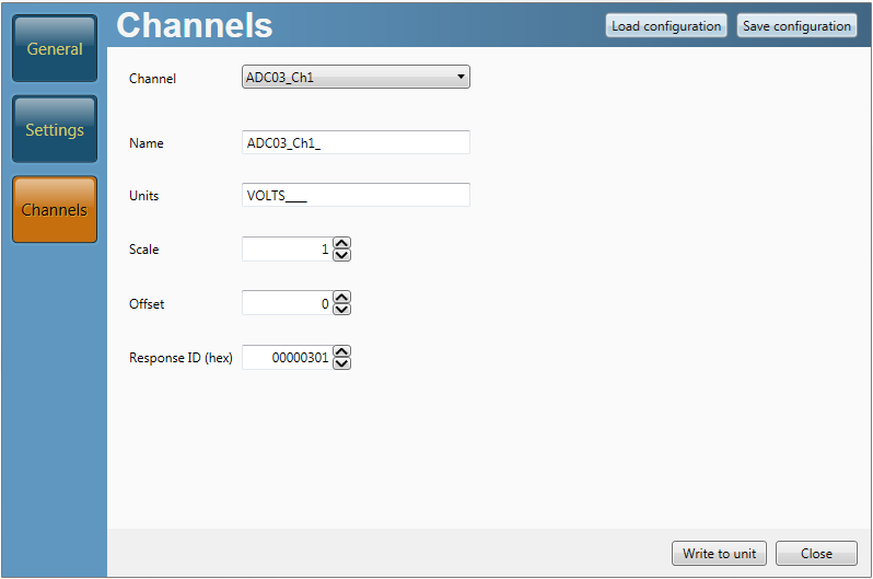
Request and Response Identifiers
The Request Identifiers only have an effect in User Polled CAN Mode. They set the identifier values that the module will filter for. If a CAN message is received that matches a Request Identifier then the module will respond by sending the corresponding channel data on the corresponding Response Identifier. Note: All channels can have the same Request Identifier – this means that on receipt of a single CAN message the module will respond with all channels of data. The Response Identifiers MUST all be different.
In Timed Mode the channel data will be sent at intervals with the corresponding Response Identifier – the Request Identifiers have no effect.
When using Standard Identifiers the maximum value for the identifiers is $7FF. Entering a value higher than this may result in unexpected results, for instance a Response Identifier of $00FFAA23 will result in a message being sent with Identifier $223. To avoid anything unexpected the request and response identifiers should be set appropriately for use with Standard Identifiers by observing the range of values in the Setup Parameters Table.