Mounting - IMU03/YAW03
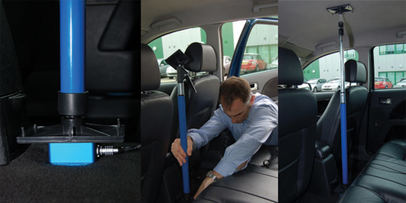
Option 1: Using a Mounting Arm
A flexible way to fix the IMU rigidly within the vehicle is by using the Racelogic Mounting Arm. The three-part telescopic handle is fully adjustable to any length between 70 and 150 cm to which another 20 cm can be added by extending a third section using the compression lever.
Both ends are fixed to an 8 cm x 13 cm plate which sits on a joint to accommodate for uneven surfaces. Pressed against the IMU on the floor and the vehicle's ceiling, the mounting prop ensures that the IMU is fixed tightly.
Please contact vbox@racelogic.co.uk for more information or to order a mounting arm (RLACS212)
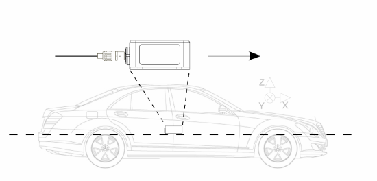
Option 2: Fixed Mounting
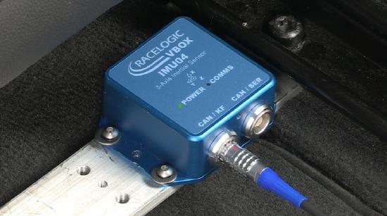
It is also possible to fix the IMU firmly to the body of the vehicle, mid-way along the wheelbase. Try to position the unit as close as possible to the centre of the vehicle, making sure it is mounted in the direction of travel - as shown in the image below. It is also important to mount the sensor so that it is level with the ground.
For best results, mount the IMU and GNSS antenna as close to each other as possible. For example: Bolt the IMU to the seat rails and place the GNSS antenna on the roof directly above.
Note: The IMU and antenna should be mounted on the same rigid body, to provide a relative reference. So for a vehicle such as a truck cabin, both the IMU and antenna should be fitted to the cabin body (if cabin is air-sprung) or to the vehicle chassis.
|
|
|
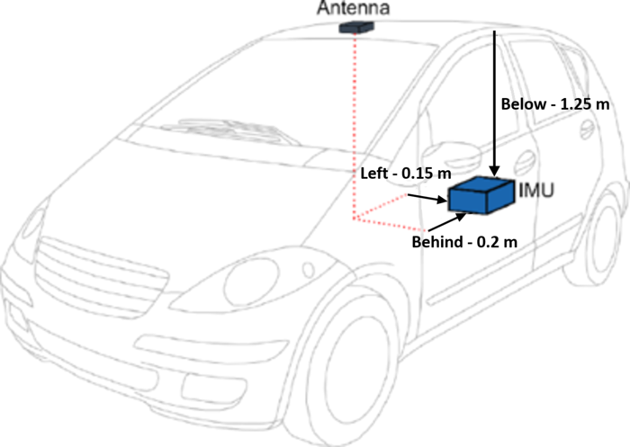
Measuring IMU-Antenna Offsets
|
When using either a fixed mounting point or the mounting arm, you must measure the relative position of the IMU in relation to the antenna* to at least within +/- 5 cm. These distances must then be entered into the VBOX unit in VBOX Setup or by using VBOX Manager. These measurements are required when using either an IMU04 or an IMU03 unit. *When using a twin antenna system, these measurements must be taken from the primary antenna (A). |
 |
Important notes when using ADAS Setup
- If using IMU filter with ADAS mode, the GNSS antenna and IMU must be co-located (roof mount) or positioned so there is no relative X or Y offset between them. If there is a difference, manual contact points should reference the IMU location, rather than the GNSS antenna.
- When using IMU Filter the user cannot use 'SET POINTS' functionality to define contact points in 1, 2 or 3 target ADAS modes.