Installing the Visual Sensor
 |
 |
Mounting the Visual Sensor
|
When you are mounting the Visual Sensor, you can choose the mounting method that best suits your testing scenario. It is, however, important to make sure that the light source you wish to test is the only light hitting the sensor during the test. To stop bleeding light from entering the sensor, we are supplying padded stickers for the bottom of the sensor, including some with double-sided tape for easy mounting. If you are mounting the sensor on an uneven or rounded surface, you may wish to apply dark tape around the edges to stop light from bleeding through and reaching the sensor. Note: The padded stickers have holes in them. When you are applying the padded sticker to the bottom of the sensor you must make sure that the hole is aligned with the actual sensor. |
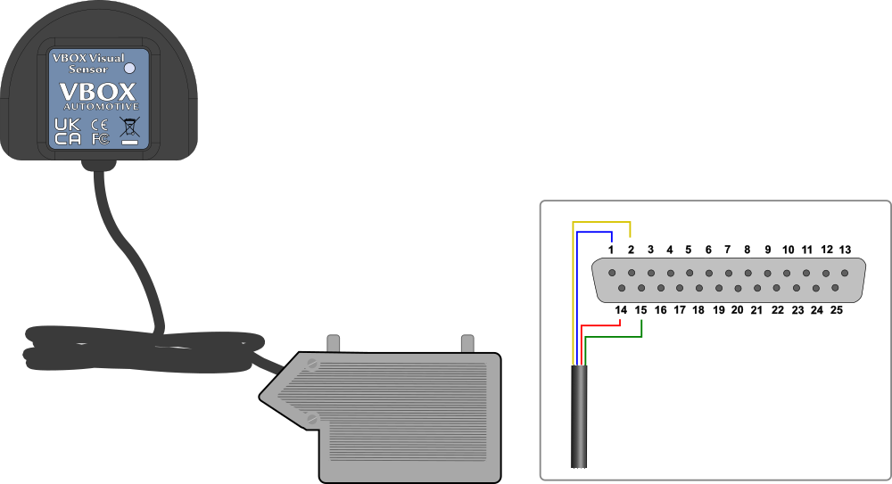
Wiring into a 25-way D-connector
Pinout Description
| Wire Colour | Function | |
|---|---|---|
| Red | Power |  |
| Green or Black* | Ground | |
| Yellow | Signal Ground | |
| Blue | Signal |
*Depending on hardware version.
Wiring Diagram
Connection to VBOX 3i Units
