02 - Connecting the Pedal Force Sensor to VBOX Data Loggers
VBOX 4
To connect the Pedal Force Sensor to a VBOX 4, please follow the steps below:
- Connect the supplied 4-way Lemo cable (RLCAB148) to the port on the rear of the Pedal Force Sensor.
- Wire the unterminated end into the required 15-way D-sub connector.
- Connect and fix the 4 wires as follows:
- Wire the green wire to the ground pin (15).
- Wire the red wire to the power pin (9).
- Wire the yellow wire to a negative pin in an available Isolated Channel pair.
- Wire the blue wire to a positive pin in an available Isolated Channel pair.
In this example, we are using channel 4 for the signal wires.
You can find the pin information for the analogue Input connector on VBOX 4 here.
- Attach the top side of the connector block housing and fix in place with the 2 screws.
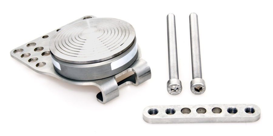
- Place the Pedal Force Sensor on top of the vehicle's pedal and secure using the bolts and back plate provided (a 6 mm Hex key is required).
Notes: - Two lengths of bolts are supplied to accommodate different-sized pedal arms.
- On some pedals, you may need to remove the rubber cover for the mounting plate to get a firm fix.
- Make sure that the sensor is firmly attached to the pedal before use.
- Plug the cable in to the A IN port on the VBOX and tighten using the thumb screws.
- The setup described above will input on the channel VB3i_AD1, please ensure the channel has been configured through VBOX Setup in order to obtain understandable results.
VBOX 3i
To connect the Pedal Force Sensor to a VBOX 3i, please follow the steps below:
- Connect the supplied 4-way Lemo cable (RLCAB148) to the rear of the Pedal Force Sensor.
- Wire the unterminated end into the required 15-way D-sub connector.
- Connect and fix the 4 wires as follows:
- Wire the green wire to the ground pin (15).
- Wire the red wire to the power pin (14).
- Wire the yellow wire to a negative pin in an available Isolated Channel pair.
- Wire the blue wire to a positive pin in an available Isolated Channel pair.
In this example, we are using channel 1 for the signal wires.
You can find the pin information for the analogue Input connector on VBOX 3i here.
- Attach the top side of the connector block housing and fix in place with the 2 screws.
- Place the Pedal Force Sensor on the top of the vehicle's pedal and secure using the bolts and back plate provided (a 6 mm Hex key is required).
Notes: - Two lengths of bolts are supplied to accommodate different-sized pedal arms.
- On some pedals, you may need to remove the rubber cover in order for the mounting plate to get a firm fix.
- Make sure that the sensor is firmly attached to the pedal before use.
- Plug the cable in to the A IN port on the VBOX and tighten using the thumb screws.
- The setup described above will input on the channel VB3i_AD1, please ensure the channel has been configured through VBOX Setup to obtain understandable results.
|
|