07 External IMU Integration - VBOX 3iS Single Antenna RTK (v1)
Instead of using the internal IMU on the VBOX 3iS, you can integrate an external IMU04. An external IMU04 will perform the same functions as the internal IMU, but it can be more beneficial in certain circumstances, such as if an IMU04 is already mounted on the test car or if the VBOX 3iS is unable to be firmly mounted in the vehicle.
You can either mount an external IMU04 on the roof of the vehicle or inside the vehicle.
If you mount the IMU on the roof, you can translate the data from the roof to another point on the vehicle. When roof-mounted is enabled, a 1 m Z offset will automatically be added to translate the filtered speed down into the vehicle and towards the centre of gravity.
If the Kalman Filter data is required relative to an alternate or more precise location on the vehicle, you should make the measurements from the centre of the IMU to the desired location. As the IMU is housed in an enclosure, it is not easy to make precise measurements. We recommend that you take the Z measurement from the centre of the GPS antenna (provided that 3 cm is subtracted from the physical measurement). Any translation measurements must be made on all 3 axes, X, Y and Z.
Required Equipment
- VBOX 3iS
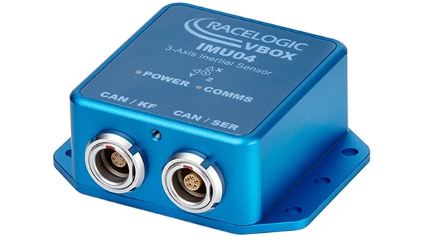
- IMU04
- RLCAB129 - VBOX 3iS Braking Cable or RLCAB130 - VBOX 3iS ADAS Interface Cable
- RLCAB131 - External IMU Interface Cable
- RLACS216 - Magnetic roof mount or RLACS256 - Suction roof mount or RLACS212 - Mounting arm or Mechanical fixings
- VBOX Setup Software (optional)
- VBOX Manager (optional)
Setup
Hardware
IMPORTANT
The IMU04 must be connected to the VBOX 3iS before you apply power. This is to ensure that the data is correctly synchronised.
- Fit your VBOX 3iS in the test vehicle, and mount the IMU as described here.
- Connect the antenna to the VBOX 3iS.
- Use the RLCAB131 cable to connect the left-hand 'CAN/KF' port on the IMU to the 'EXT.IMU' lead of the cable loom connected to the VBOX 3iS.

- Measure the Antenna to Ref/IMU Offsets. You can find more information on this here.
- Roof Mounted: If required, take data translation measurements in X, Y and Z axis from centre of IMU. This is by default set to 1 m directly beneath the IMU when Roof Mount is 'Enabled'.
- In-vehicle mounted: Measure the relative position from the top centre of the GNSS antenna to the top centre of the IMU. You must measure all 3 axes, X, Y and Z.
- After the IMU04 is connected, you can apply power to the VBOX 3iS.
- Enable External IMU Integration and enter the Antenna to Ref/IMU Offsets. You can do this using the VBOX Setup Software, the Front Panel of the unit, or with VBOX Manager.
Configuration
You can configure external IMU Integration via the VBOX Setup Software, the Front Panel of the unit, or with VBOX Manager.
Note: When mounting the IMU04 on an angle, the raw accelerometer and gyro data will be incorrect as these channels are not pitch compensated.
IMPORTANT
The IMU04 must be in a Racelogic CAN mode to be used for IMU Kalman Filter.
Initialisation
When you are using IMU integration, you must perform an initialisation phase when you first connect the IMU after setting up your VBOX 3iS.
This will automatically run through after the VBOX unit has gained satellite lock. When the initialisation process is complete, 'Stationary Initialisation Complete' will display on the front panel for 2 seconds before displaying 'Waiting For Movement'.
IMU04 LED Indicators
| IMU04 LED Colour | Power | Coms |
|---|---|---|
| Red | Initial boot up phase | No coms |
| Orange | Temperature checks. If the temperature is outside the optimum operation range, LED will remain orange. | Using IMU integration, inertial data is sent to host VBOX via RS232. |
| Green | Fully operational. | Inertial data is being sent to the host system via CAN. |