Connecting VB3i to a Gregory Fuel Flow Sensor

If you are intending to connect a Gregory Fuel Flow Sensor to a VBOX 3i, there are two options available; you can either connect the sensor to a modified Frequency Input Module, or connect the sensor to a Mini Input Module and VBOX 3i.
IMPORTANT - If you are intending to use a Frequency Input Module, a standard unit cannot be used! Please confirm that you will be using the FIM03 with a Gregory Fuel Flow Sensor when ordering to ensure the unit is modified correctly.
Modified Frequency Input Module Connection
 |
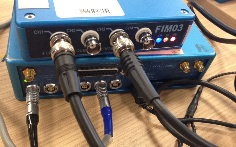 |
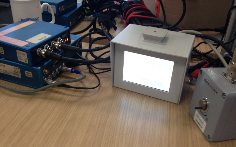
- Using a BNC to BNC connection cable, connect the 'TTL OUT' port of the Gregory Fuel Flow Sensor to the 'CH1' port of the Frequency Input Module.
- Using a BNC to BNC connection cable, connect the 'ANA OUT' port of the Gregory Fuel Flow Sensor to the 'CH3' port of the Frequency Input Module.
- Using a RLCAB005 cable, connect the 'CAN' port of the VBOX 3i to socket '1 (CAN/POWER IN)' or '2 (CAN OUT)' of the Frequency Input Module.
- Using a RLCAB066-2 cable, connect the 'USB' port of the VBOX 3i to a PC USB connection.
- Apply power to all connected units.
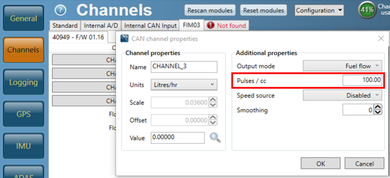
- Using VBOX Setup, navigate to 'Channels', then 'FIM03' and configure Channels 1 and 3 for Fuel Flow Modes (substituting Channel 2 in the instructions for Channel 1).
- Ensure the 'Pulses / cc' additional property matches the TTL scale on the Gregory Fuel Flow Sensor.
Mini Input Module Connection
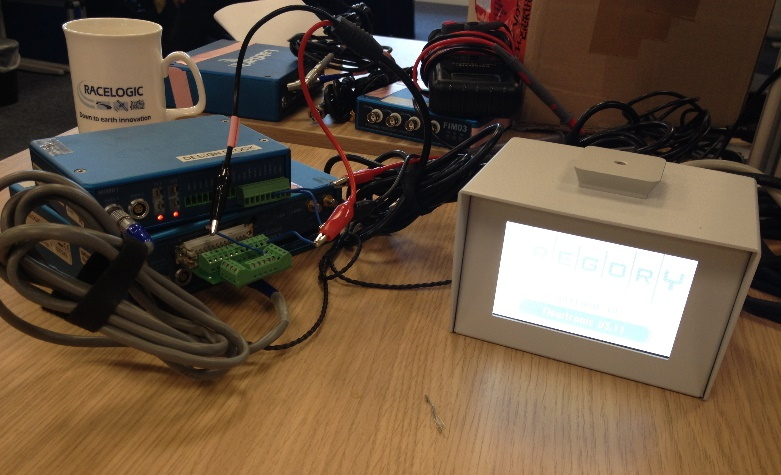 |
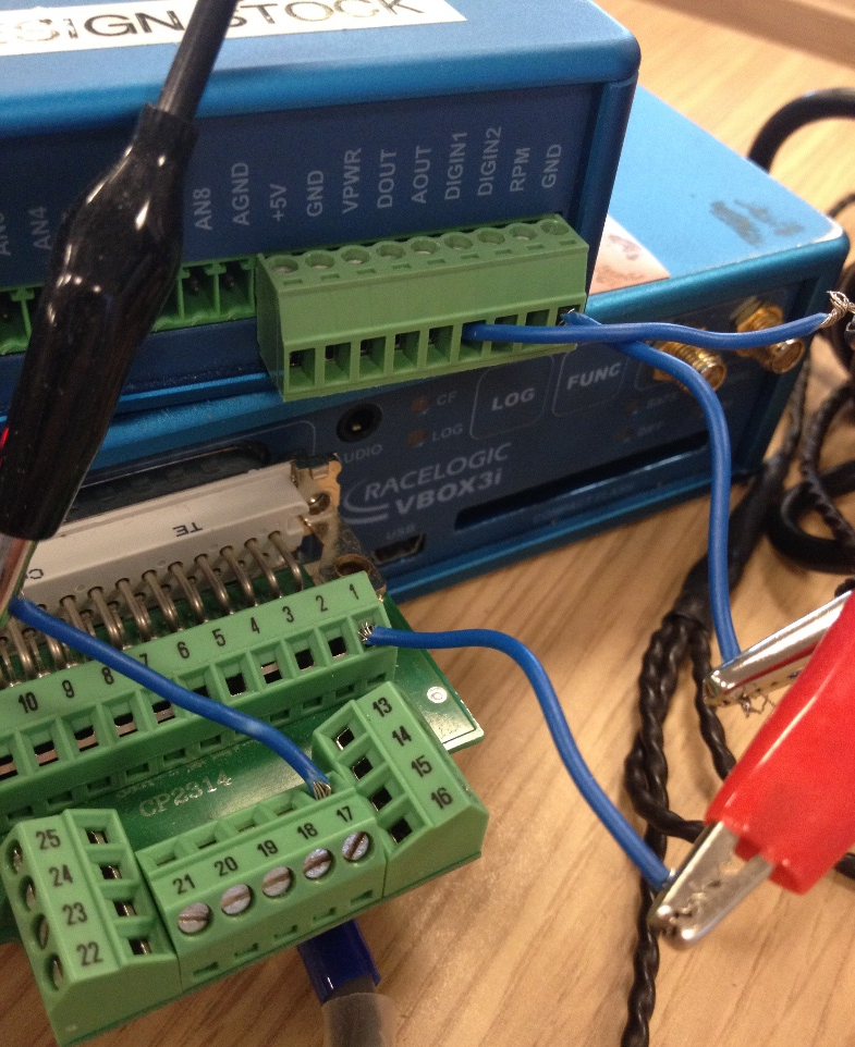 |
- Using a BNC to dual crocodile clips connection cable, connect the 'TTL OUT' port of the Gregory Fuel Flow Sensor to the Mini Input Module.
- Connect the red crocodile clip to the 'DIGIN1' port of the screw terminal via a single wire connection.
- Connect the black crocodile clip to the 'GND' port of the screw terminal via a single wire connection.
- Using a BNC to dual crocodile clips connection cable, connect the 'ANA OUT' port of the Gregory Fuel Flow Sensor to the VBOX 3i.
- Connect the red crocodile clip to the 'A IN PIN 1' port of the screw terminal (ADC25IPCON) via a single wire connection.
- Connect the black crocodile clip to the 'A IN PIN 17' port of the screw terminal (ADC25IPCON) via a single wire connection.
- Using a RLCAB005 cable, connect the 'CAN' port of the VBOX 3i to socket 'DATA1' of the Mini Input Module.
- Using a RLCAB066-2 cable, connect the 'USB' port of the VBOX 3i to a PC USB connection.
- Apply power to all connected units.
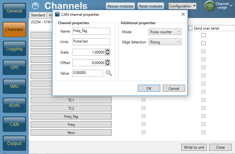
- Using VBOX Setup, navigate to 'Channels' and configure the 'Freq_Tag' channel within 'Input Modules' as below.
