01 Introduction

Configuration
VBOX 3i can be configured using VBOX Manager via a RLCAB005 cable, or can be connected to a computer and configured using VBOX Setup software. You can connect to a computer via Bluetooth, a RLCAB001 cable to the 'SER' input and the computer's serial port (USB-serial adapter may be required), or via a RLCAB066-2 cable to one of the computer's USB ports.
For ADAS applications, connection between the VB3i and computer should be made via USB or Bluetooth to ensure optimum performance.
Power Supply
Included with the VBOX 3i is a cigar lighter power cable, which is the primary source of power input. This is terminated in a 2-way connector and mates with the 2-way ‘PWR’ socket on the VBOX 3i.
The VBOX 3i can be powered from a wide range of voltage sources. When considering batteries as a power source, please note that the minimum operating voltage of the VBOX 3i is 7 V. The maximum operating voltage input must not exceed 30 V DC. Failure to observe this could result in damage to the VBOX.
Note - Using an External Power Backup prevents the system shutting down under temporary power loss.
|
Warning The VBOX can be connected to other Racelogic input modules including the ADC03, ADC02, TC8, FIM02/3 and multifunction display. Please note that the voltage supply to Racelogic modules connected to the VBOX will be at the same level as the VBOX power input. Therefore, when using any of the Racelogic peripherals with VBOX 3i, the input voltage must not exceed 15 V. Failure to observe this could result in damage to the module and possibly the VBOX 3i. |
When running the VBOX from a battery pack, the VBOX will sound a warning tone to indicate when the battery voltage is reaching the minimum operating voltage level. When this tone is heard, the battery pack requires re-charging or replacing.
The VBOX 3i has been designed to generate as little heat as possible, and it has a wide operating temperature range. However, it is good practice to mount the VBOX 3i in a position where it has sufficient airflow around the case.
You must connect the GNSS antenna before connecting power to the VBOX 3i. This is necessary because on power-up the VBOX 3i will look for a connected GNSS antenna and automatically adjust its gain for optimum performance.
RACELOGIC external modules operate from a 12 V vehicle supply. Therefore, when using external modules, VBOX supply must not exceed 15 V DC.
Hardware Variants
VBOX 3i is available in three variants:
- VB3i: A single antenna version, offering position accuracy of up to 50 cm.
- VB3iD (formerly VB3iSL): A dual antenna version including the same features as VB3i but with the addition of a second GNSS Antenna, meaning it can also measure slip angle, pitch/roll angle and heading at 100 Hz.
- VB3iDR (formerly VB3iSLR): A dual antenna version with RTK, offering centimetre level position accuracy and multi-vehicle/ multi-target ADAS testing.
Along with an extra antenna socket for dual antenna systems, variants can also be identified using the product label sticker on the side of the unit.
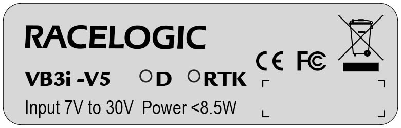 VB3i label |
 VB3iD label |
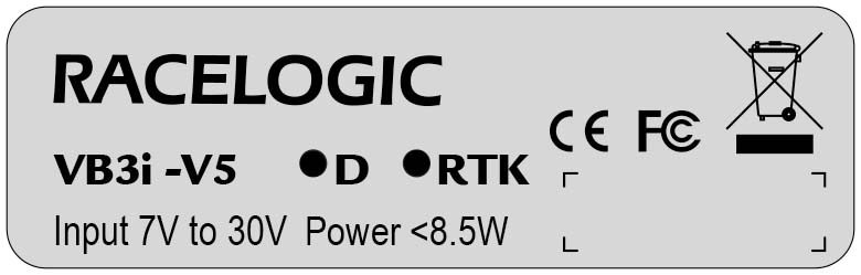 VB3iDR label |
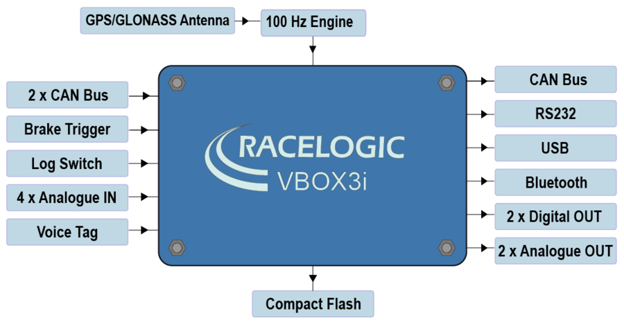
Inputs/Outputs
VBOX 3i (VB3i)
VBOX 3i Dual Antenna (VB3iD)
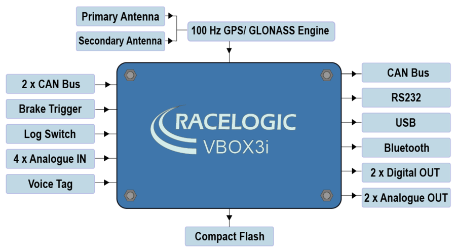
VBOX 3i RTK (VB3iDR)
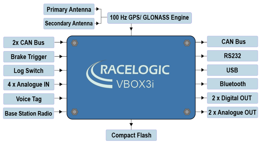
Inputs
- 100 Hz GPS / GLONASS Engine
VBOX 3i features a powerful GNSS engine capable of providing 100 Hz signal update rate for all GPS/GLONASS parameters (i.e. velocity, heading and position). Velocity and heading are calculated via Doppler Shift in the GNSS carrier signal, providing you with unparalleled data accuracy. - GPS/GLONASS Antenna(s)
All standard parameters like time, speed, distance, and position are measured at the primary antenna. The secondary antenna (dual antenna systems and VBOX 3i V4G only) enables logging of additional channels like slip angle, pitch or roll angle (depending on antenna orientation). - Base Station Radio Link (RTK systems only)
Can be used in conjunction with an RTK differential Base Station to obtain centimetre-level positional accuracy. - 2x CAN Bus
Two CAN Bus interfaces are available; a Racelogic CAN bus and a customer VCI bus. The Racelogic CAN bus is designed to interface with Racelogic external modules, such as TC8, FIM03 and IMU04. The customer VCI bus is designed to connect third party CAN devices, to log additional VCI CAN data to the VBOX (i.e. vehicle CAN bus, Steering wheel sensor). Having separate CAN bus connections allows the user to connect to separate CAN data sources without risk of re-broadcast on to customer VCI source. 64 external CAN channels can be logged by the VBOX, of which up to 32 CAN channels can be logged from Racelogic modules, up to 16 CAN signals can be logged on the VCI customer bus and up to 64 CAN channels can be logged from other channels. When logging data from another source, VBOX Setup software can be used to load signal data from an industry standard CAN database file (.DBC). - Brake Trigger
By using a physical pressure switch on the brake pedal, a precise 'start of braking event' can be captured. The brake/event trigger input is oversampled to 25 ns for high distance accuracy. - Log Switch
A start/stop logging switch allows users to manually choose when they wish to record data. - 4x Analogue Inputs
Each of the four analogue input channels has a dedicated analogue converter. Data is recorded from each channel simultaneously to avoid latency between analogue channel data. The name, scale and offset of each analogue input channel can be adjusted using VBOX Setup software to allow sensor calibration and therefore logging of data in standard SI units. The analogue input connector also provides two power outputs that may be used for driving sensors. These are in the form of a 5 V DC supply and an output equal to the VBOX power supply voltage. If the VBOX is set to 100 Hz log rate, then the additional option of 500 Hz analogue data sampling will be present and available. - Voice Tagging
VBOX 3i can record a GNSS synchronised WAV audio tag of up to 30 seconds long, captured to a time accuracy of 0.5 sec. The recorded WAV file is then logged to the CF card. - Power Supply
VBOX 3i can accept a supply voltage between 7 – 30 V DC. Low current consumption results in extended battery life.
Outputs
- CAN Bus
The VCI customer CAN bus can be utilised to output standard VBOX data parameters, plus up to 12 additional data channels from connected external source or internal modules (i.e. ADAS, dual antenna).
The baud rate and CAN ID's for these outputs are user configurable. - RS232
The RS232 connector is used for VBOX configuration and output of real-time GNSS data. Provides the facility to connect to a radio telemetry system to offer PC monitoring of test data. - USB
VBOX 3i USB connector can be used for VBOX configuration and to output real-time data at 100 Hz to a PC. - Bluetooth
VBOX 3i comes equipped with an internal Bluetooth Radio, allowing remote configuration and remote output of real-time GNSS data to any Bluetooth capable PC or Data logger. The Bluetooth connection is capable of sending data at the full 100 Hz rate. - 2x Digital Outputs
The first digital output is assigned to 'Speed/Distance' with adjustable 'Pulses per Meter' setting, while the second output is a level switch output enabling users to select any one of the logged channels and assign it a threshold value, e.g. output high (5 V) when speed greater than 20 kmh. - 2x Analogue Outputs
Both 16 bit analogue outputs can be configured to output any data channel being logged by the VBOX for use by additional data logging equipment. The voltage output range is from 0 to 5 V DC, with a resolution of 76 μV per bit. - CF Card
Data is logged in a space-delimited text format. Recording time dependent on flash card capacity, log frequency, number of channels and logging conditions. Approximately 29 MB per hour used when logging GNSS data at 100 Hz; approx. 182 MB per hour total logging capacity.
Note: Large VBO files may cause issues when loading into VBOX Test Suite, depending on PC specification. The higher the set recording frequency, the larger the logged data file will be.
Technical specifications vary for each VBOX 3i version. Please see the datasheets for detailed information.