4.3 CAN
Racelogic CAN Bus
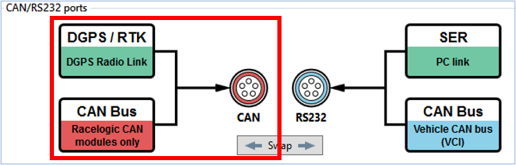
The Racelogic CAN bus connection (CAN port by default) can be used to connect Racelogic modules (i.e. TC8, FIM03 etc), and displays such as VBOX Manager and Multi-Function Display. This port will allow the VBOX 3i to log up to a maximum of 32 Racelogic module channels.
Note: For the Racelogic CAN port, it is recommended that the CAN Termination resistor is on.
Note: VBOX 3i has an additional channel limit of 64. Additional channels consist of VCI channels (up to 16), RL CAN channels (up to 32) and any other channels that fall outside the channels on the Standard tab in VBOX Setup, such as AD inputs, IMU KF channels, Twin antennas channels, ADAS channels and so on.
Channel selection is controlled using VBOX Setup. Additional channels can be logged by the VBOX 3i up until the point the Log channel usage is maxed (100%)
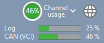
Channel usage
The log channel usage is influenced by what operational mode the VBOX 3i is in. For example, if the IMU filter is enabled, the number of channels available to log will be reduced.
CAN channel availability – Multi-Function Display
A Multi-Function Display (RLDSP03) can display any channel that is present on the Racelogic CAN bus, and in the first 32 CAN channel ordering.
First 32 CAN channel ordering priority goes to any external data source. Therefore if there are 32 external channels set to log by the VBOX 3i, no internal module channel will be present for selection on the MFD.
CAN channel availability – send over serial
Same as the MFD, a data channel must be in the first 32 CAN channel ordering for the VBOX 3i to send out data over serial to a ‘live data window’ on VBOX Test Suite.
First 32 CAN channel ordering priority goes to any external data source. Therefore if there are 32 external channels set to log by the VBOX 3i, no internal module channel will be present for selection on the MFD.
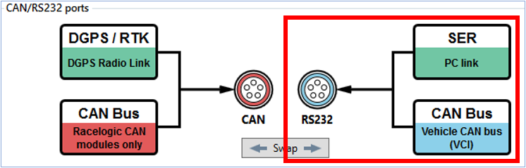
VCI Input (Vehicle CAN Interface)
The Vehicle CAN bus (VCI) connection (SER port by default) can be used to connect to a vehicle CAN or a sensor CAN bus. This port will allow VBOX 3i to log up to a maximum of 16 channels.
Note: For the VCI CAN port, it is recommended that the CAN Termination resistor is off when connected to a vehicle's CAN bus.
Configuration is performed using the Internal CAN Input tab in the Channels menu within VBOX Setup software. CAN signal parameters can be entered manually by the user or imported directly from a CAN database (.dbc) file if available.
Racelogic Vehicle CAN Database
Racelogic supplies a free, encrypted vehicle CAN database, giving the user the ability to log basic CAN data from a large number of current vehicles from a broad selection of manufacturers.
All of the CAN database files for vehicles we have reverse engineered can be downloaded from our website.
Please note to access these downloads you will need a username and password - to retrieve this, please register (or re-register) your VBOX unit.
VB3i CAN Pass Through
It is possible to output channel data from the Racelogic CAN bus (i.e. Racelogic modules such as TC8) on the isolated customer VCI bus. The user can configure output data (in VBOX Setup) using channels from the available channels dropdown list, and configure the identifier as required.
Example application: Racelogic IMU connected to the Racelogic CAN bus to use IMU yaw rate for improved dual antenna slip translation data. Same IMU data being transmitted from the customer VCI bus to be logged by third party CAN logging equipment.
The VBOX 3i can output up to 6 user configured CAN messages, and 12 CAN channels over the customer VCI bus.
Be aware of checking CAN pass through channel selection when re-entering VBOX Setup. If the VBOX has many external CAN channels being logged, then the dropdown channel selection can re-adjust. When VBOX Setup is then exited, the adjusted CAN channels will be applied.
Note: If you are loading VB3i configuration settings from a previously saved .RCF file and external modules were connected during the save, selected CAN pass through channels may not be reloaded correctly. Please check and directly configure the channels through VBOX Setup.
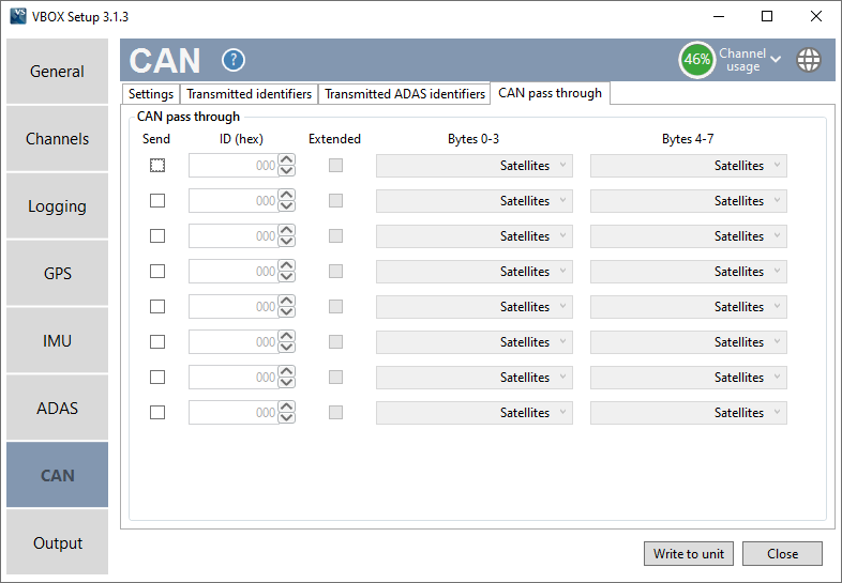
Note: These output CAN channels will be in a 32 bit IEEE float format. 29 bit extended identifiers optional.
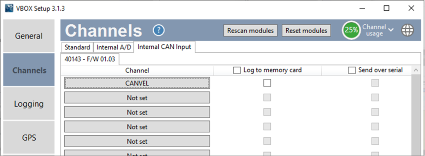
VB3i CANVEL
If an input channel is given the name 'CANVEL', then the VBOX will translate the data of this channel directly through to the GPS speed channel under the following criteria.
- IMU integration is not enabled
- The VBOX cannot calculate speed, i.e. no satellite signal (complete satellite drop out)
The VBOX will scale the input channel to the default speed output format of km/h according to what units have been assigned to the substitution speed channel. VBOX will recognise the following unit names: MPH, KM/H, Knots, m/s, and ms-1.
Note: If no UNITS have been assigned to the input channel then VBOX will assume that it is KM/H.
This function is useful while testing around built up areas or driving under large bridges.
VB3i CAN Termination
The VBOX 3i contains an active termination between 0 Ohms and 120 Ohms, the active terminations are selectable via VBOX Setup as shown below.
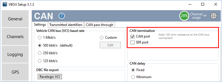
Note: When the Usage of the CAN ports is swapped from one output socket to the other the termination resistor setting does not follow. So you should check that the Termination is correctly set for the output socket that you are then using.
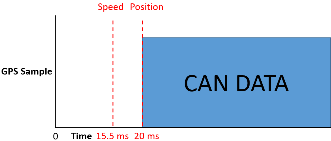
VB3i CAN Delay

When to Use the Fixed CAN Delay?
‘Fixed CAN Delay’ is recommended for use when using an external event marker or trigger, or for other external CAN devices that require precisely timed CAN outputs. This is the default setting.
‘Fixed’ and ‘Minimum’ CAN Delay
When CAN Delay is set to ‘Fixed’, the speed delay is 15.5 ms and the position delay is 20 ms. When CAN delay is set to ‘Minimum’, the speed delay is 4 ms (±1 ms) and the position delay is 8.5 ms (±1.5 ms). The data comes out faster in the ‘Minimum’ setting, but the delay is unpredictable.
Note: Do not use Minimum CAN Delay mode if you are using a lot of Racelogic input modules connected to the CAN bus as the variability of the output could cause loss of samples from the modules.
Fixed CAN Delay Example
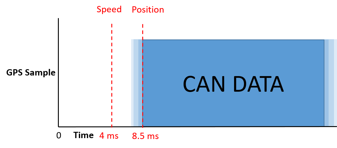
Minimum CAN Delay Example
CAN Delay with IMU Integration
When IMU Integration, the CAN Delay is automatically set to ‘Fixed’; the speed and position delay is 20 ms.
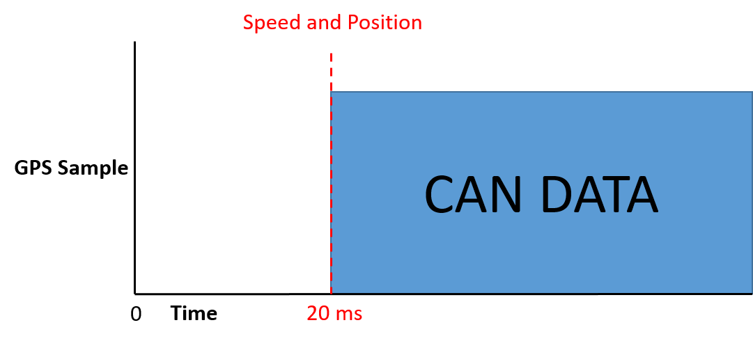
IMU Integration CAN Delay Example
ADAS Modes
The ADAS modes will add the following delays to the standard CAN output (20 ms if you are using Fixed delay):
- 1 Target Mode (no Moving Base) = 50 ms
- 1 Target Mode (Moving Base) = 60 ms
- 2 Target Mode (no Moving Base) = 50 ms
- 2 Target Mode (Moving Base) = 60 ms
- 3 Target Mode (Moving Base or no moving base) = 80 ms
- Static Point = 0 ms
- Lane Departure = 0 ms
- Multi static point = 0 ms
Note: The above numbers are for v2.8 Firmware on VBOX 3i.