Inputs/Outputs - VBOX 3i Dual Antenna (v5)
Inputs
Analogue Inputs
You can see the pinout information for the Analogue Input Connector here.
VBOX 3i Dual Antenna units contain four differential 24-bit analogue input channels with a maximum sample rate of 500 Hz (2 channels if it has an A version number in the product code, e.g. VB3i-V5A). Each channel has its own dedicated analogue to digital (A/D) converter with all four channels being sampled synchronously to each other. The voltage range of the input channels is ±50 V.
Note: The analogue channels in the VBOX 3i units are not electrically isolated from each other.
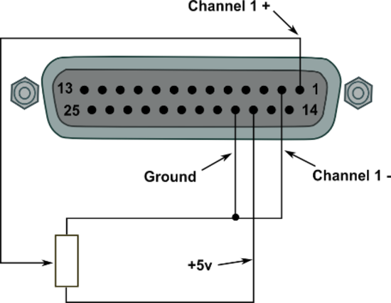
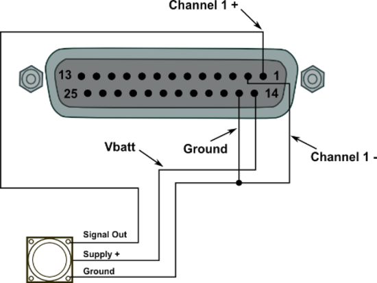
The analogue input connector also contains voltage outputs that can be used to power external sensors. These are a Vbatt connection that equals the VBOX unit's input voltage level and a 5 V DC out connection that equals 5 V ±2%.
- The 5 V out connection is electrically isolated, allowing for a current draw of up to 120 mA.
- The Vbatt connection is internally protected by a thermal fuse of 300 mA.
A screw-terminal connector block is available as an option for easy connection of signal pins.
 |
 |
Note: A 25 W D-sub to 4 W BNC adaptor block is available through your VBOX distributor, part number RLVBACS054.
By using VBOX Setup software you can change the name of each input channel and configure scale and offset values for calibration of sensors. A scale value of 1 and an offset of 0 correspond to a channel reading in V DC. This means that the value stored on the compact flash card for the channel will also be in volts. When using a sensor such as a load cell, it may be desirable to store readings in kg. In this case, changing the scale and offset to suit the sensor data sheet allows the data stored on the compact flash to be in kg. When changing settings for an analogue channel in the VBOX Setup software, you can see a live data view of the current channel. The value shown is the value after scale and offset are applied and can, therefore, be used to aid sensor calibration.
Note: The 5 V regulated output on pin 16 is only good for VBOX power supply voltages > 8.5 V.
 |
| AD channel properties in the Channel Config menu in VBOX Setup |
500 Hz logging
VBOX 3i units have the ability to log 4 analogue channels at 500 Hz. With this feature enabled, the file sizes will increase. You can enable 500 Hz logging for internal analogue and digital inputs in VBOX Setup, in the Logging menu.
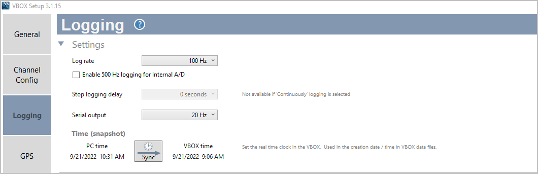 |
| VBOX Setup A/D 500 Hz |
Digital Inputs
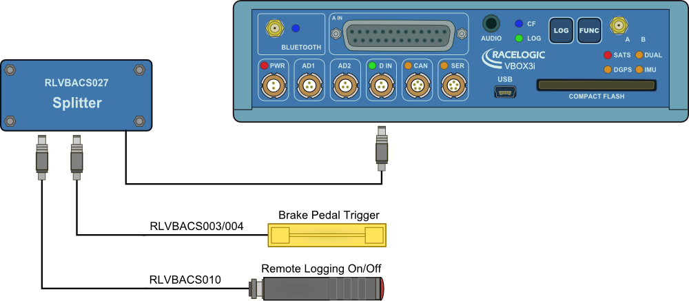
Log SwitchA start/stop logging switch allows users to manually choose when they wish to record data. Brake Trigger/Event MarkerBy using a physical pressure switch on the brake pedal, a precise ‘start of braking event’ can be captured. The ‘D IN’ connector contains the two digital inputs for VBOX 3i units. See the example image below.
|
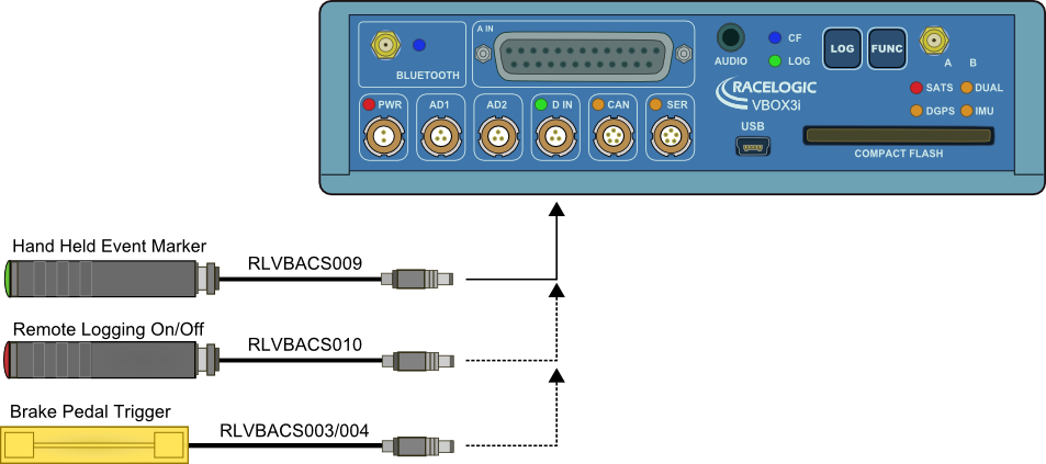 |
| You can connect two digital input devices to the VBOX 3i with the use of an additional splitter box, as shown in the example image below. |
 |
Outputs
CAN Bus
One of the two VBOX CAN ports can be used to output VBOX GPS parameters plus any 12 channels from connected input modules or internal AD channels. The baud rate and CAN ID’s for these outputs are user-configurable.
RS232
RS232 connector is used for VBOX configuration and output of real-time GPS data. Serial data sent to the software is limited by the bandwidth of the PC serial port – 20 Hz (Full 100 Hz serial is available via USB / Bluetooth).
USB
You can use the USB connector on the VBOX 3i units to configure the VBOX and output real-time data at 100 Hz.
Analogue and Digital Outputs
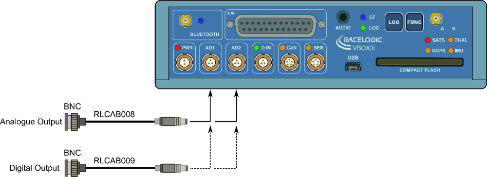
Analogue
2 x 16-bit analogue outputs can be configured to output velocity (or other GPS parameters) for use by additional data logging equipment. The voltage output range is from 0 to 5 V DC with a resolution of 76 μV per bit.
Digital
Two digital outputs are available. One Digital output is assigned to Speed/Distance – configurable via Pulses per Meter. The second is a level switch output enabling users to select any one of the logged channels and assign it a threshold value.
Bluetooth
VBOX 3i units comes equipped with an internal Bluetooth Radio allowing remote configuration and remote output of real-time GPS data to any Bluetooth-capable PC or Data logger. The Bluetooth connection can send data at the full 100 Hz rate.