03 Front Panel

Buttons
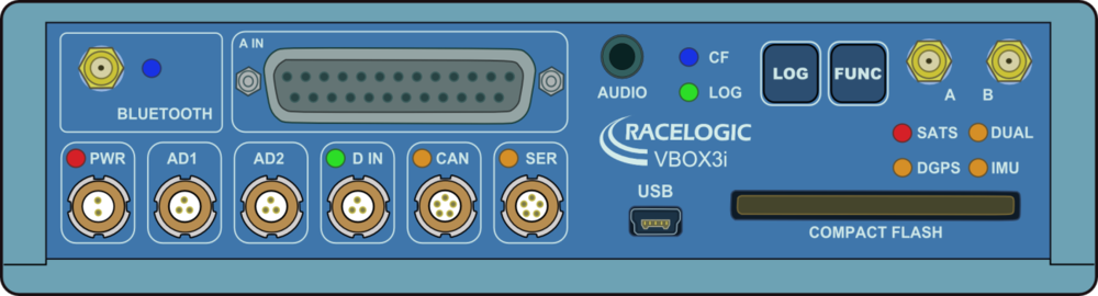
VBOX 3i has two membrane buttons on the front panel, LOG and FUNC. LOG is used to start and stop logging to the compact flash card, and FUNC is used to switch between two sample rates, 100 Hz and 20 Hz.
LOG
The LOG button will override any of the automatic logging thresholds set in the VBOX. For example, if you have set the VBOX to log all the time, the LOG button will toggle logging on and off. If you have set the VBOX to ’log only when moving’ and you are moving, pressing the LOG button will stop the VBOX logging and close the file on the compact flash. Logging will now not continue even if you are moving until the LOG button is pressed again or the compact flash card is removed and reinserted. The VBOX will then continue to log only when moving. Note that if the VBOX is using ‘log only when moving’ log mode, and the vehicle has been stationary from power-up, the LOG button will not initiate logging. If you want the VBOX to log, you would have to use VBOX Manager or VBOX Setup to change the log mode to ‘Log Continuous’.
- Every time the logging is toggled with the LOG button, a new file is created.
- When the VBOX is logging, the the green LOG LED will be solid and the blue CF light will flash.
Important - Do not remove the CF card or power down whilst the CF LED is flashing. If you need to remove the card or power down whilst the CF LED is flashing, then press the LOG button first to stop the VBOX logging. Failure to do so will result in data loss or corruption.
FUNC
Pressing the FUNC button briefly flashes the LED’s and beeps to indicate the current sample rate. A slow flash (once per second) on all the LED’s indicates 20 Hz, and rapid flashing (5 times a second) indicates a 100 Hz sample rate. A running sequence of lights indicates a sample rate other than 100 Hz or 20 Hz. Pressing and holding the FUNC button for 5 seconds toggles the current sample rate. The sample rate can also be set using VBOX Manager or VBOX Setup.
Default setup
The default factory settings are restored to the VBOX by pressing and holding the FUNC and LOG buttons for 5 seconds. This will put the VBOX 3i into the default factory settings; 100 Hz log rate, log continuous mode, Fixed 20 ms CAN delay, Output CAN Tx Identifiers on, Racelogic CAN on the CAN port, customer VCI CAN on the SER port, and only standard GPS channels and brake trigger event time set to log.
VB3i RS232 / CAN Ports
Click here for information on the VB3i RS232 protocol.
VBOX 3i is equipped with 2 CAN Bus interfaces and 2 RS232 serial ports. The primary RS232 port is used for all communication between the VBOX and laptop PC. The primary port is marked SER on the VBOX 3i front panel. The primary RS232 port (SER) is able to transmit live data from the VBOX to the PC for viewing and performing real-time tests. It is important to note however that due to limitations of the PC serial port, live data transfer of all channels is limited to 20 Hz, at 50 Hz only standard GPS channels and Solution Type should be transmitted, and at 100Hz only Sats, Time, Speed, and Trigger Event Time should be transmitted. Logging too many channels at too high a rate is likely to cause drop-outs and loss of data.
Therefore for maximum accuracy, tests performed at a GPS sample rate above 20 Hz should be logged to compact flash and post processed.
Note that when the VBOX is set to an ADAS mode, RS232 serial transmit from the SER port will be disabled.
The secondary RS232 port is used for connection to a Telemetry Radio module allowing the reception of Differential GPS (DGPS) data for local correction from a Racelogic Local DGPS basestation, or Moving Base solution. The secondary RS232 port is located in the connector marked CAN on the VBOX 3i front panel.
The CAN Bus ports A and B are located in the VBOX 3i connectors “CAN” and “SER” respectively. The function of these ports is configurable by the user using VBOX Setup to toggle the Racelogic Bus profile. The Racelogic CAN bus is used for connected Racelogic modules or displays. The Vehicle CAN bus (VCI) is for use by third party CAN equipment, whether logging to the VBOX, or logging from the VBOX. For dual use of RS232 and CAN from one of the sockets you will require a 5 way Lemo splitter RLVBACS024.
Power supplied to external Racelogic CAN modules through the “CAN” or “SER” cables is at the same voltage as the input power supply. Therefore when using Racelogic external CAN modules (eg; MFD or ADC03), the VBOX 3i supply voltage must not exceed 15 V DC.

USB
The VBOX includes a USB 2.0 connection that can be used for VBOX configuration and the output of real-time serial data at the full 100 Hz data rate.
Before you connect your VBOX to your PC ensure that you have downloaded and installed VBOX Setup software, as this will also put the required USB drivers onto your PC.
The software installation will place the VBOX USB drivers in the following location on your computer. C:\program files\Racelogic\Drivers.
VB3i drivers can also be downloaded from the Drivers and Utilities section of vboxautomotive.co.uk. You can find more information about how to install the drivers here.
When you connect a powered up VBOX 3i to your PC with the supplied USB lead, your PC will recognise the presence of new hardware and open the typical Windows install window for new hardware. Follow the on screen prompts and point the Windows installation to the location of your drivers.