5.5 IMU Menu
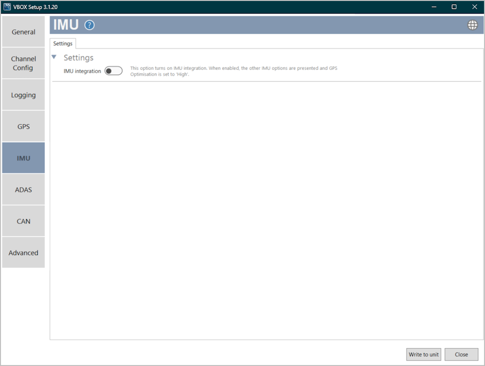
The IMU Integration will be disabled by default. Use the toggle switch to enable the IMU integration. When this is enabled, the IMU settings will become available and the GPS Optimisation will automatically be set to High.
IMU Integration Enabled
Settings
|
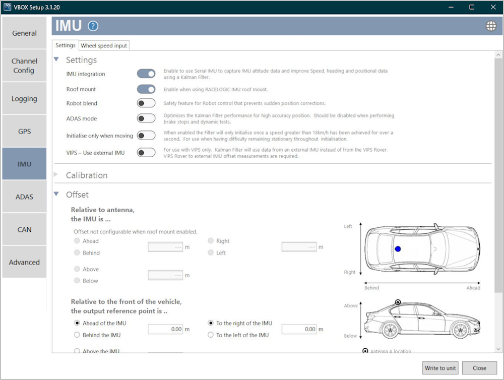
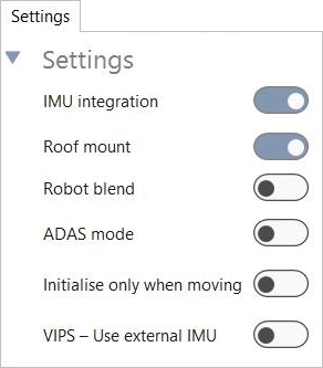
IMU integration Use the toggle switch to enable/disable IMU integration. When enabled, you can use Serial IMU to capture IMU attitude data and improve accuracies for speed, heading and positional data. Roof mount Use the toggle switch to enable/disable the roof mount feature. This should only be enabled when you are using a Racelogic Roof Mount. Robot blend Use the toggle switch to enable/disable the Robot Blend feature. This is a safety feature for when you are using robot control. It prevents sudden position corrections and provides a smooth return of position and heading. ADAS mode Use the toggle switch to enable/disable the ADAS mode feature. This optimises the Kalman Filter's performance for high-accuracy position. This feature should not be enabled when you are performing brake stops and dynamic tests. Initialise only when moving Use the toggle switch to enable/disable the Initialise only when moving feature. This will make the filter initialise only when the unit detects a speed that is faster than 18 km/h for a second or longer. You should use this feature in scenarios where you find it difficult to remian stationary during the initialisation. VIPS - Use external IMU Use the toggle switch to enable/disable the VIPS feature. Note: This is only to be used if you are using a Racelogic VIPS product. You can find more information about using this feature in the VIPS documentation. |
 |
||
Calibration
 |
|
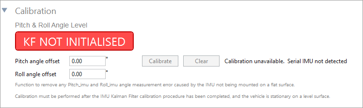
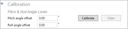
Pitch & Roll Angle level The function of the Pitch and Roll Angle Level is to remove any measurement error on the Pitch_imu and Roll_imu channels caused by the IMU not being mounted on a flat surface. Click the Calibrate button to start the automated calibration process. |
 |
|
|
Notes:
Click Clear to remove any set offset values. |
||
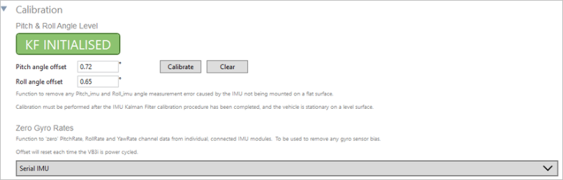
Zero Gyro Rates
These rate offsets are used to correct any gyro bias, making the Pitch, Roll and Yaw channels read zero when the vehicle is stationary.
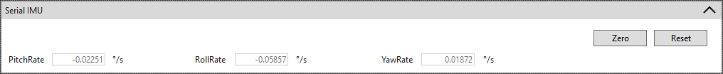
You can expand the Serial IMU section to view the live values for Pitch Rate, Roll Rate and Yaw Rate and to find the Zero function for the Gyro Rate Offsets.
 |
|
Click the Zero button to calibrate the rate offsets for all detected and available IMUs. The software will run through an auto-calibration procedure for each available IMU. Click the Reset button to remove the calibrated offsets and reset the rates to the default values. |
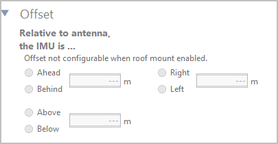
Offset
Relative to antenna, the IMU is …
|
When you have set Roof Mount to 'Disabled': You must enter the offset values (X, Y and Z) from the IMU to the antenna. These are needed for the Kalman Filter algorithm. |
 |
|
When you have set Roof Mount to 'Enabled': The Antenna to IMU offset becomes greyed out and you can no longer enter any values (see image). |
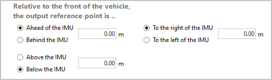
Relative to the front of the vehicle, the output reference point is …
|
Enter the X, Y, and Z offset values from the nominated reference point to the IMU. This will translate the data from the IMU location to the point on the vehicle where all the measurements will be made. |
 |
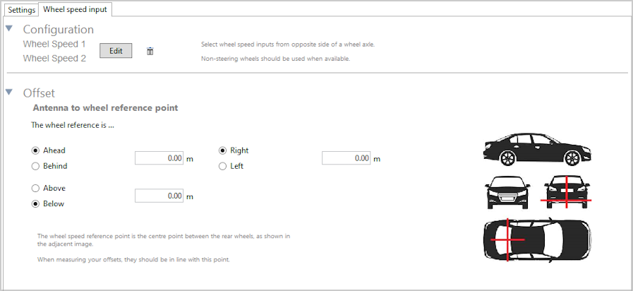
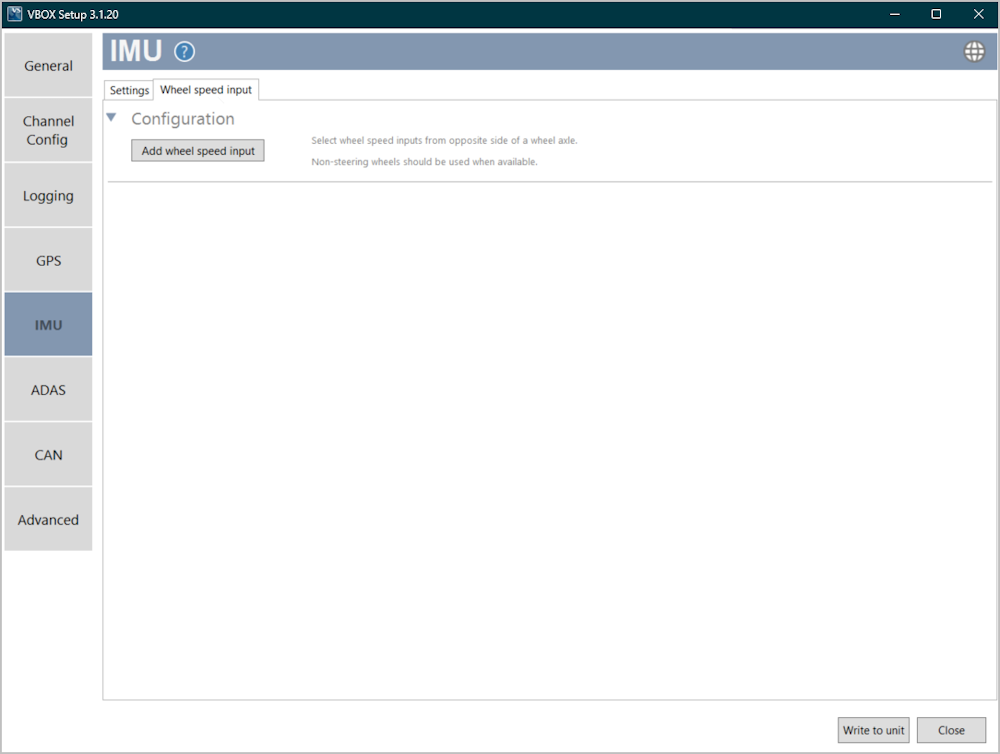
Wheel Speed Input
 |
|
Note: This tab is only presented when IMU integration is Enabled. You can use the wheel speed input options to configure the wheel speed input channels and the reference location. Adding wheel speed information in the Kalman Filter can improve positioning in locations that are subject to obstruction, such as tunnels or other areas where there is no view of the sky at all. Inertial sensors and wheel-speeds can fill in the gaps for periods of up to 5 minutes. |
Configuration
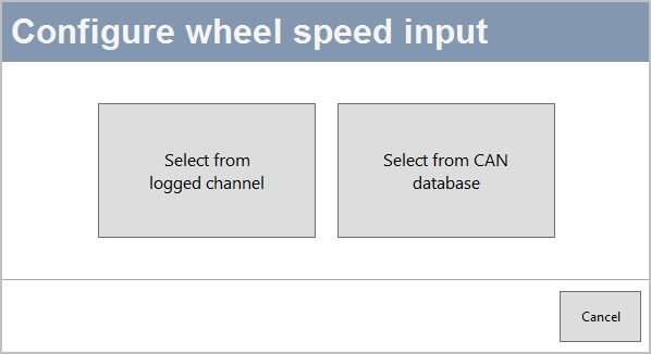
Select from logged channel
You can set the wheel speed inputs with an already configured CAN input channel. You will be able to pick a channel from a list of available channels connected to the SER port (the set CAN input port if you are using a CAN Hub).
Select from CAN database
You can select channels to use for wheel speed from the internal database or from a database file.
Click the Add wheel speed input button to open the Select wheel speed input channels window and set your input channels.

Select the User radio button to choose wheel speed input channels from a user-configured database file.
Select the Vehicle database button to choose wheel speed input channels from the internal vehicle database.
Make – Use the dropdown menu to see a list of available makes and select the one that applies to your setup.
Model – Use the dropdown menu to see a list of all available models and select the one that applies to your setup.
The Connection details area will provide you with available CAN connection information for the selected vehicle.
The Wheel Speed 1 and 2 sections will display lists of available options for Wheel Speed 1 and 2, based on your selection in the vehicle database or your database file.
Offset
After configuring your wheel speed inputs, you must measure and enter the offset from the antenna to the wheel reference point. The Wheel Speed reference point is the centre point between the rear wheels. Make sure that your measurements are in line with this point.