5.8 Advanced Menu
Output Tab
 |
|
The Output Tab is where you can configure the digital and analogue signals on the AD outputs. You can:
|
Output settings
Digital
|
|
|
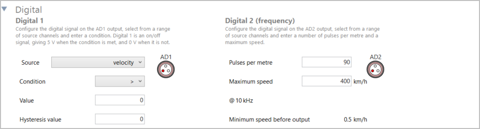
Digital 1 Configure the digital signal on the AD1 output, select from a range of channels currently being logged by the VBOX unit and enter a condition. Digital 1 is an on/off signal, giving 5 V when the condition is met, and 0 V when it is not. Source This is a dropdown menu with the available source signals based on standard VBOX 3i channels and A/D inputs. Condition This is a dropdown menu with the following conditions:
Value You can specify a threshold value so that the output is 5 V if the condition is true or 0 V if it is false. Hysteresis value You can also apply a tolerance or hysteresis value, depending on the specified condition. |
Digital 2 Configure the digital signal on the AD2 output, select from a range of source channels and enter a number of pulses per metre and a maximum speed. Pulses per metre Enter the number of pulses you want for your output. Maximum speed Enter the maximum speed you want for your output. @ 10KHz This value is the maximum output frequency based on the values in the Pulses per metre and Maximum speed settings. Minimum speed before output Based on the values you have entered above and the set update rate, the software will calculate a minimum speed before output. |
Analog
|
|
|
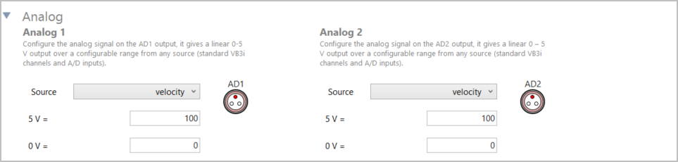
Configure the analog signal on the AD1 and AD2 output, including the source and the 5-Volt value and 0-Volt value. This provides a linear 0-to-5-Volt output over a configurable range from any source (standard VBOX 3i channels and A/D inputs) Source This is a dropdown menu with the available source signals based on standard VBOX 3i channels and A/D inputs. 5 V = and 0 V = You can scale the signal output to best suit the test conditions by setting the 5 V = and 0 V = options to the required limits. |
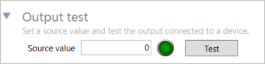
Output testYou can test the digital and analogue outputs without the need to connect an antenna and move the vehicle. Source value Enter and apply a speed, which will force the digital and analogue outputs to give a relative output value. Test Click on the Test button to start the output test and click on the Stop button to stop the output test. |
 |
Local Coordinates Tab
 |
|
The Local Coordinates tab in the Advanced menu is there for you to survey and see the local co-ordinate frame (X and Y position) used for the channel calculations. You will be able to:
Survey You can survey the origin, track direction and coordinates. Click Survey to set the coordinates to the location of the antenna for your VBOX unit. Clear Clear an already surveyed location. |
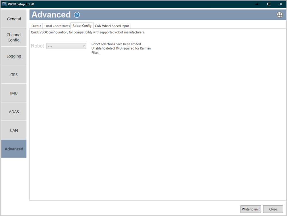
Robot Config Tab
 |
|
Configure VBOX 3i Single Antenna to integrate with supported third-party robots. You will be able to select options based on compatibility with your connected hardware. Note: By enabling a robot mode, your VBOX unit will expect certain settings. |
CAN Wheel Speed Input Tab
 |
| Configure the CAN Wheel Speed Input by adding the channels you wish to use. |
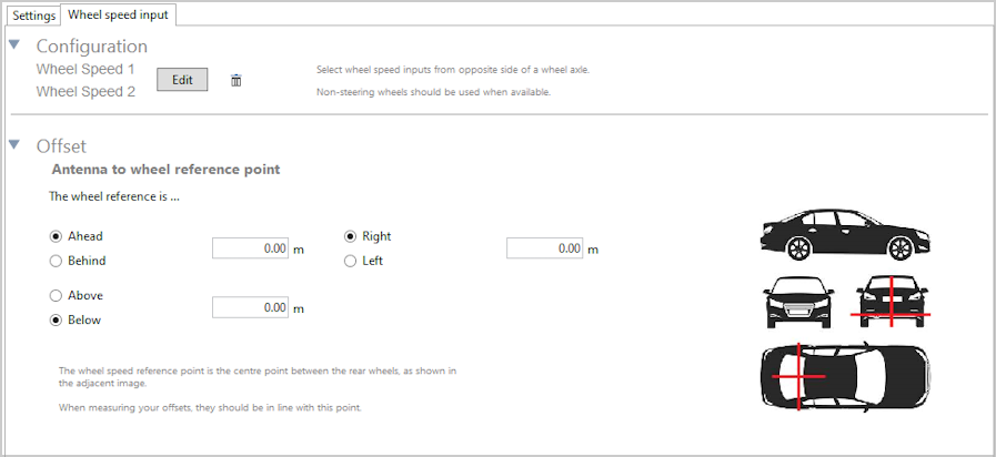
Wheel Speed Input Configuration
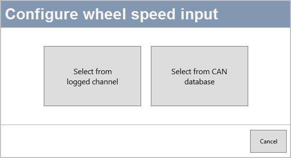
Select from logged channel
You can set the wheel speed inputs with an already configured CAN input channel.
Select from CAN database
You can select channels for wheel speed from the internal database or from a database file.
Click the Add wheel speed input button to open the Select wheel speed input channels window and set your input channels.

Select the User radio button to choose wheel speed input channels from a user-configured database file.
Select the Vehicle database button to choose wheel speed input channels from the internal vehicle database.
Make – Use the dropdown menu to see a list of available makes and select the one that applies to your setup.
Model – Use the dropdown menu to see a list of all available models and select the one that applies to your setup.
The Connection details area will provide you with available CAN connection information for the selected vehicle.
The Wheel Speed 1 and 2 sections will display lists of available options for Wheel Speed 1 and 2, based on your selection in the vehicle database or your database file.
Offset
After configuring your wheel speed inputs, you must measure and enter the offset from the antenna to the wheel reference point. The Wheel speed reference point is the centre point between the rear wheels. Make sure that your measurements are in line with this point.