Advanced
Output Tab

Digital

Digital 1 |
Digital 2 |
Pulses Per Metre |
Source |
Maximum Speed |
Condition |
@ 10KHZ |
Value |
Minimum Speed Before Output |
Hysteresis Value |
Analogue

Analogue 1 and 2
Source
- 5 V = and 0 V =
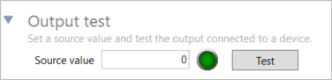
Output Test
 |
|
Source Value |
|
Test |
Local Coordinates Tab

Survey
Clear
Robot Config tab

CAN Wheel Speed Input Tab

Configuration
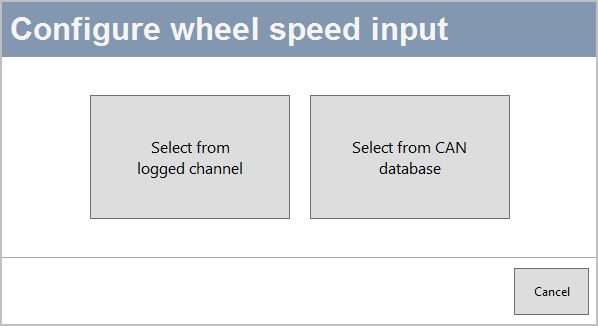
Select from logged channel
You can set the wheel speed inputs with an already configured CAN input channel.
Select from CAN database
You can select channels for wheel speed from the internal database or from a database file.
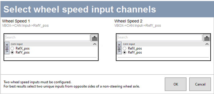
Click the Add wheel speed input button to open the Select wheel speed input channels window and set your input channels.

Select the User radio button to choose wheel speed input channels from a user-configured database file.
Select the Vehicle database button to choose wheel speed input channels from the internal vehicle database.
Make – Use the dropdown menu to see a list of available makes and select the one that applies to your setup.
Model – Use the dropdown menu to see a list of all available models and select the one that applies to your setup.
The Connection details area will provide you with available CAN connection information for the selected vehicle.
The Wheel Speed 1 and 2 sections will display lists of available options for Wheel Speed 1 and 2, based on your selection in the vehicle database or your database file.
Offset
Send Over Serial Tab

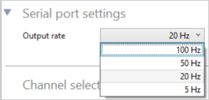
Serial Port Settings
Output Rate
 |
Channel Selection
 |