07 - VBOX 20SL3 Triple Antenna Placement

Whilst installation and use of the VB20SL3 is intended to be fast and simple, careful attention must be paid to placement of the antennas.
Note: It is essential that the separation of Antenna B and Antenna C from Antenna A is exactly the same as the separation values set inside the VB20SL3 via the configuration screen. If the separation is incorrect, data may not be given or may be inaccurate. The measured distance between the antennas should be the straight-line distance between the antennas regardless of the mounting angle. It is not the 2D distance between the antennas as viewed from above.
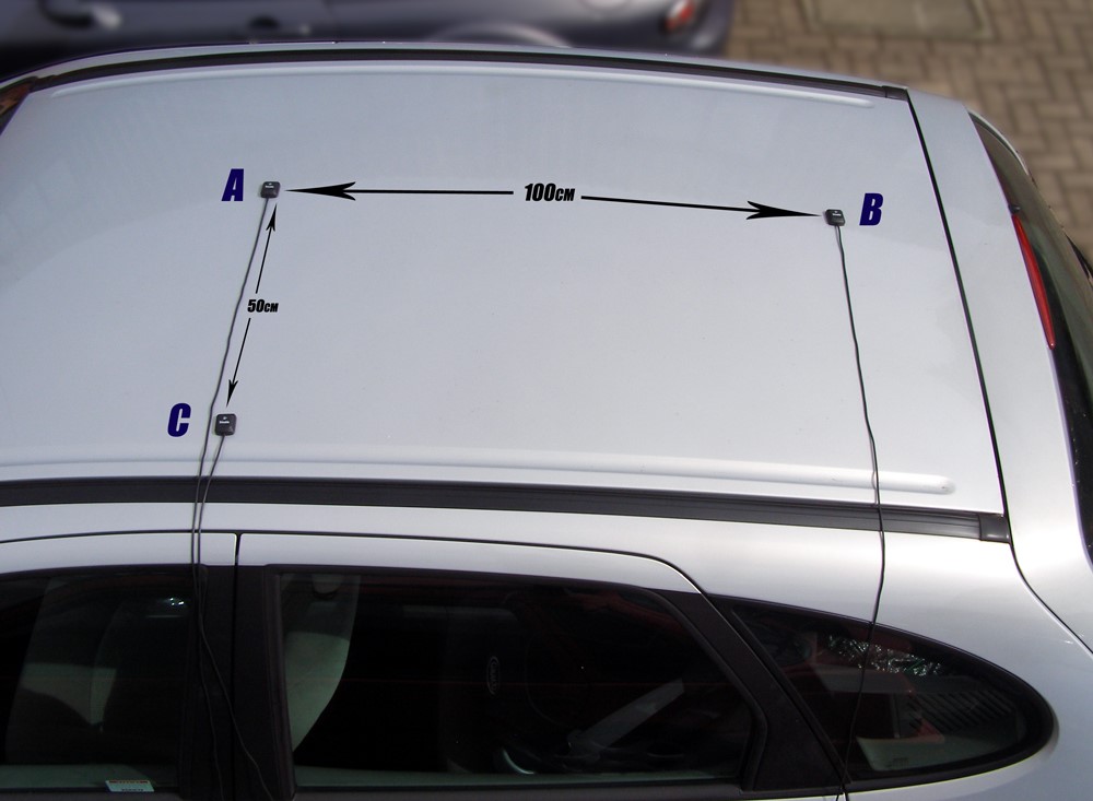
The picture above shows a typical 3-antenna placement for the measurement of Body Slip Angle, Pitch and Roll angle. Antenna A the primary antenna is placed in the centre of the roof. Antenna B is placed behind Antenna A, allowing True heading, Slip angle and Pitch Angle to be measured. Antenna C is placed to the side of Antenna A allowing the measurement of Roll angle.
Antenna A is the primary antenna, from which all calculations are based. If overall slip is to be measured (at the centre of the vehicle), the primary antenna should be placed at the centre of the vehicle. Alignment of the antennas is not completely essential as the Slip Angle Sensor has the ability to calculate any offset. See the Slip Angle Offset Section.
However if you wish to measure Pitch or Roll then the alignment of the antennas must be in line with the vehicle or at 90oas accurately as possible.
When measuring Slip angle Antenna B can be placed either in front or behind Antenna A. If it is placed behind Antenna A as in the picture above then the ‘Swap Antenna’ option needs to be enabled in the Antenna configuration options.
When measuring Slip angle at a specific point on a vehicle (for example over a given wheel), the primary Antenna A must be placed over this point on the vehicle.
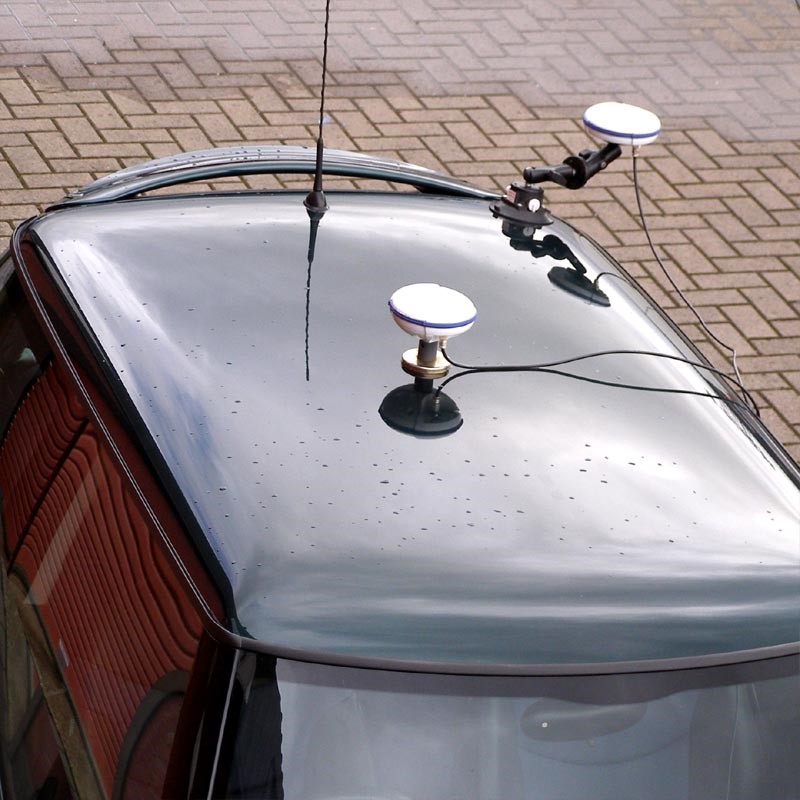
GPS antennas require a ground plane to operate correctly. Usually, the metal roof of a vehicle performs this function. However, if a test requires an antenna to be placed off of the vehicle, then a special Ground Plane ‘mushroom-style’ antenna must replace the off-vehicle antenna, as these antennas are capable of operating without a ground plane.
If a vehicle roof also has obstacles such as roof bars then Ground plane antennas should be used as they can be mounted higher than the obstacle.
The Ground Plane ‘mushroom’ style antennas RLVBACS065 are available from your VBOX distributor.
If only one antenna will be placed ‘off-vehicle’ then only one Ground Plane antenna need be purchased.
Antenna Separations >2 m
When the antenna separation is >2M it is advised where possible to mount the antennas as level as possible so that the ‘LEVEL’ option can be enabled, otherwise the RTK lock is not so reliable and the Slip and Roll/Pitch data can drop out or become intermittent.
The VB20SL must only be used with the supplied antenna, unless instructed otherwise by Racelogic.
GPS Antenna
The GPS Antennas supplied with the VB20SL3 are 3.5v active antennas. For the best possible signal quality, it is important to maintain a clean connection between the antennas and the VBOX. Before fixing the antennas to the VBOX, ensure that there are no dust particles in either connector. Replacement antennas are available by contacting your VBOX distributor.
The antenna is a magnetic mounting type for quick and simple mounting to the vehicle roof. For optimum GPS signal reception, make sure that the antenna is fitted to the highest point of the vehicle away from any obstructions that may block satellite reception. The GPS antenna works best with a metal ground plane underneath (eg. Vehicle roof).
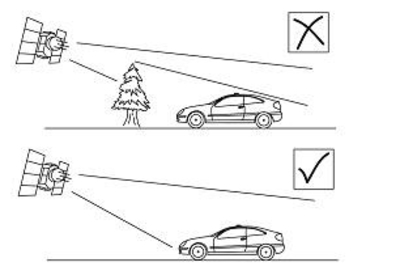
Please also note that when using any GPS equipment, a clear sky view is important. Objects in the surrounding area such as tall buildings or trees can block the GPS signal causing a reduction in the number of satellites being tracked, or introducing reflected signals that can decrease the accuracy of the system.
NOTE: VB20SL3 can struggle with maintaining an RTK lock required for Slip, Pitch and Roll measurement if the antennas are placed too close to Roof Bars. If a poor mounting position cannot be avoided then use Ground plane antennas, RLVBACS065.
.jpg?revision=1)
Using the VB20SL3 With One GPS Antenna
The VB20SL3 can be used like a traditional VBOX. Only Antenna A is needed if the VB20SL3 is to be used like a traditional VBOX without the requirement to measure Slip, Pitch, Roll, YAW rate and Lateral Acceleration channels.
For single antenna use (for standard, non-slip GPS data), the antenna should be connected to the Ant A connector.
Velocity can be output on either the Analogue or Digital outputs.
See the table below for the GPS data available with each antenna configuration.
| Antenna combinations | Sats | Time | Latitude | Longitude | Velocity | Heading | Height |
|---|---|---|---|---|---|---|---|
| A |  |
|
|
|
|
|
|
| A+B | |
|
|
|
|
|
|
| A+C | |
|
|
|
|
|
|
| A+B+C | |
|
|
|
|
|
|
| Antenna combinations | Vertical Velocity | True Heading | Slip Angle | Pitch Angle | Yaw rate | Lateral Velocity | Roll Angle |
|---|---|---|---|---|---|---|---|
| A | |
 |
|
|
|
|
|
| A+B | |
|
|
|
|
|
|
| A+C | |
|
|
|
|
|
|
| A+B+C | |
|
|
|
|
|
|
The VB20SL3 has a brake trigger input so not only can the VB20SL3 measure and output Velocity it can measure and output Trigger Velocity, Trigger to zero Time and Trigger to zero Distance. This data is logged to SD card and available on the CAN bus or USB/serial connection bus along with all the other GPS data.
NOTE: When measuring a braking distance the GPS optimisation must be set to High and the Kalman filter Velocity parameter set to 0 (zero), via the front panel controls or the VBOX Tools software.