08 - VBOX 20SL Slip/Roll Angle Offsets

Slip Angle Offset
When using the VB20SL3 for measurement of Slip Angle, Pitch and/ or Roll Angle, True Heading, Lateral Velocity or Yaw Rate, it is essential that the Slip Angle offset is determined before conducting tests. This then compensates for any misalignment in the placement of Antennas A and B.
There are also many occasions when the antennas cannot be placed directly in line with the car, such as when an ‘off-vehicle’ antenna is used to measure the Slip angle over a particular wheel.
Measuring Pitch Angle and Slip Angle
To measure Pitch angle accurately at the same time as Slip angle with Antennas A and B will require the antennas to be aligned as close as possible to a line parallel to the longitudinal line of the car.
Setting the Slip Offset
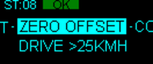
The VB20SL3 includes a built-in facility for calculating and setting the offset. With the antennas placed suitably and the antenna separation set correctly in the unit, enter the Setup Antenna configuration menu and select Slip offset ‘Calc. Offset’. The unit will give instructions on its display screen to allow it to determine the offset.
First, the unit will instruct you to drive at a speed greater than 25 km/h. Once this is achieved, the unit will tell you to drive straight, and will begin calculating the Slip Angle offset automatically. During the 5 second process, it is very important that you keep the vehicle in a straight line and above 25 km/h. The Slip angle sensor beeps during this calculation and then stops beeping when it has finished calculating the offset.
If required, the Slip Angle offset can be re-calculated at any time by repeating this procedure. Selecting the ‘Clear Offset’ option in the Configuration Screen will clear the current offset value.
Please note that the unit will need to have a full RTK lock to perform this procedure – if the orange ‘RTK’ light is flashing, the procedure cannot be initiated.
Pitch / Roll Angle Offset
It is not always possible to mount the antennas on a vehicle so that they are perfectly level. In order to compensate for non-level antenna placements you should use the Pitch and/or Roll offset facility, which will automatically compute and then use an offset compensation.
Measuring Roll angle:
To measure Roll angle accurately with Antennas A and C will require the antennas to be aligned as close as possible to a line perpendicular 90o to the longitudinal line of the car.
Setting Pitch / Roll Offset
Press the ’■’ button to enter the Main menu then select the Setup Antenna Menu, and then select either the Pitch or Roll antenna setup menu.
From within either the Pitch or Roll antenna setup menu select either Pitch or Roll offset menu, when the screen shows ‘CALC OFFSET’ press the ’■’ to calculate a PITCH or ROLL offset.
If required, the Pitch or Roll angle offset can be re-calculated at any time by repeating this procedure. Selecting the ‘Clear Offset’ option will also clear the current offset value.
Setting Slip Angle Offset Remotely Via CAN
It is possible to request that the VB20SL3 calculates a Slip Angle Offset by sending it requests via CAN.
The CAN Baud rate is 500Kbit/s, Motorola 11 bit – Standard Frame, The DLC = 8
The VB20SL3 will respond on CAN to indicate stages of the Slip offset process and also indicate completion or failure.
Please see the table below:
| Message Type | CAN ID | Data Bytes | ||||||||||
|---|---|---|---|---|---|---|---|---|---|---|---|---|
|
0 |
1 |
2 |
3 |
4 |
5 |
6 |
7 |
|||||
| Request | Start Slip offset calculation |
0x7FE |
46 |
49 |
4C |
45 |
4D |
41 |
4E |
40 |
||
| Request | Cancel Slip offset calculation |
0x7FE |
46 |
49 |
4C |
45 |
4D |
41 |
4E |
41 |
||
| Response | Increase speed to >25 km/h |
0x7FB |
05 |
02 |
00 |
00 |
00 |
00 |
00 |
00 |
||
| Response | Drive Straight |
0x7FB |
05 |
03 |
00 |
00 |
00 |
00 |
00 |
00 |
||
| Response | Offset done – value shown in Data bytes 2-5 |
0x7FB |
05 |
01 |
3F |
9D |
70 |
A4 |
00 |
00 |
||
| Response | Offset failed |
0x7FB |
05 |
00 |
00 |
00 |
00 |
00 |
00 |
00 |
||
The Response message to indicate completion also contains the Offset value as a 32 bit IEEE float on Data bytes 2-5.
In the example above Data bytes 2 - 5 = 3F 9D 70 A4 which equals a decimal value of 1.23o
Level
The ‘LEVEL’ option should be enabled (set to YES) when the antennas are mounted within 10o of each other (from the horizontal), and not expected to exceed 10o during testing. With the LEVEL option enabled the GPS engines maintains its RTK lock more efficiently and the Slip and Pitch channels are less likely to drop out.
If the expected angle between the antennas will be greater than 10o then the ‘LEVEL’ option should be disabled (set to ‘NO’).
Note: When the antenna separation is <2 m the RTK lock is very resilient in most conditions and scenarios when the ‘Level’ option is not enabled.