04 - Coastdown SW Running Tests
Step 1: Setting up the VBOX on a Vehicle
Set the up the VBOXIII/VB3i on your vehicle as instructed in the VBOXIII/ VB3i user manual.
If an IMU is being used, connect the IMU to the VBOXIII/VB3i. Example setups are shown below – please note the IMU04 can also be used with a RLCAB005/CS or RLCAB119.
.png?revision=1)
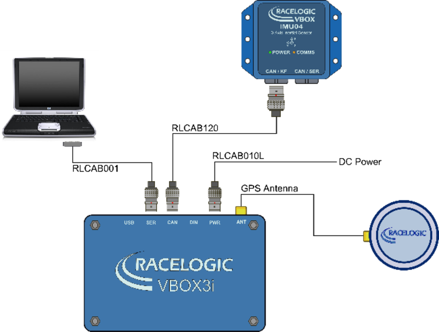.png?revision=1)
Step 2: Configuring the VBOX with VBOX Tools
Prior to setting up and performing the Coastdown test, the VBOXIII/VB3I will need to be configured to ensure that it is in the correct operating mode for the test. This is particularly important if your VBOX is used for other types of testing as well.
NOTE: Once this is done it will not need to be repeated providing that the VBOXIII/VB3i configuration does not get altered.
The following instructions should be followed using your VBOX Tools software manual as a reference.
- Open VBOX Tools software.
- Next click on the VBOX Set-up Icon. A dialogue box will open to allow you to configure the VBOX.
- Select Channels ► Standard and then ensure that all channels from listed from Satellites to Trigger event time are ticked for sending over serial and log to compact flash.
- Click the Internal A-D and VCI modules tabs to ensure that every box is unticked.
- Select the 3-axis module window and ensure that the X Accel and Y Accel boxes ONLY are ticked for ‘log to Compact flash’ and ‘sending over serial’.
- Select the Logging Tab and ensure that:
- Serial o/p is set to 20Hz
- CF log rate is set to 100Hz
- Log conditions is set to Log only when moving
- Select the GPS Tab and ensure that:
- Kalman filter velocity option is set to zero.
- GPS Optimisation – if using an IMU, this should be set to high dynamics to ensure that the IMU data is integrated when the GPS data is noisy. If you’re not using an IMU, set GPS optimisation to low dynamics to compensate for any GPS noise.
Step 3: Running the Coastdown software
- Click on the Coastdown Software desktop shortcut, to run the software.
- Ensure VBOXTools software is closed so that it does not hold the Com port.
- Open the ‘Options’ drop down menu and select the correct Com port for the Coastdown software to use.
Step 4: Aligning the IMU
If an IMU is to be used, the Coastdown software will require the use of the IMU to be enabled and its position aligned.
- Open the ‘Options’ menu and then ensure that the “Use IMU” option is ticked
- Drive the vehicle to the test track on which the Coastdown test will be performed and stop the vehicle.
- To perform the IMU alignment, click:
|
Options ►IMU ► Alignment aid. |
.png?revision=1) |
This will bring up the screen shown below. The blue dot is the position of the IMU with respect to both the X and Y axis and the red circle is a target area for the blue dot.
Physically adjust the mounting of the IMU so that the blue dot falls entirely within the boundary of the red circle – the closer this can be set to the 0 crossing of the axes the better, but to position the blue dot within the circle indicates that the IMU is within 1.8° of the horizontal and vertical axes.
With the blue dot positioned correctly, click OK. The IMU alignment data is now stored within the software.
.png?revision=1)
Step 5: Selecting a test range
- Select the required test sub-range in the test range indicator.
- If the range options are not suitable then configure the ranges to what is required for your Coastdown test. For more details see the ‘Software Configuration and Test Setup’ section of this manual.
Step 6: Starting and Running the test
- Click Start, or press F2. Your vehicle GPS speed and, if used, IMU speed will now be displayed in the speed trace window(s). In the Speed vs. Time window, the GPS speed is displayed in grey and the corrected GPS speed, incorporating IMU data, is displayed in red.
.png?revision=1)
- Accelerate to 5km/h (or mph, depending upon speed units selected) above the required sub-range start speed. During this acceleration, the test status indication will show the blue TEST ARMED box.
.png?revision=1)
- Once the Start speed + 5 has been reached, the test status will change to the yellow WAITING FOR START SPEED box. Place gearbox in neutral and start coasting, maintaining direction of travel (Direction 1).
.png?revision=1)
- When the start speed has been reached, the test status indicator will change to the green RUNNING box.
.png?revision=1)
- Continue coasting. If you have set intermediate steps in your range then the time taken to Coastdown between each intermediate speed will be displayed in the test progress table in real time.
- Continue coasting until the sub-range end speed has been reached. At this point all of the intermediate steps in the test progress table will be completed for first run, in that direction only and the green TEST RUNNING box will revert back to the blue TEST ARMED box.
.png?revision=1)
- Repeat steps 6.3 to 6.6, in the opposite direction (Direction 2).
- Continue performing steps 6.3 to 6.8. The test progress table will continually update with the average time for each intermediate section, based upon the time taken to perform the test in both directions. As the test progresses, the software will calculate, in real time, the running mean of the test averages and will also calculate the standard deviations of these means.
Based upon the standard deviation, the accuracy % will either be greater than 2%, in which case the box will have an orange fill (for at a glance identification) or less than 2%, in which case the box will turn green.
- Repeat steps 6.3 to 6.9, until the statistical accuracy for all intermediate ranges is below 2%. All Accuracy boxes will have a green background.
- Repeat steps 6.3 to 6.10 for each test sub ran.
- When the test is finished, click Stop or press F2. The test results are automatically saved as a .TXT file to your chosen directory. For instructions on how to select a Log file directory please refer to ‘Software Configuration and Test Setup’ section of this manual.