03 - MICIN Connection to VBOX
Configuring the MICIN01C when connected to a VBOX
Make sure your VBOX is connected to your computer via RLCAB01 or USB, load up VBOX Tools and select VBOX Setup on the main menu bar.
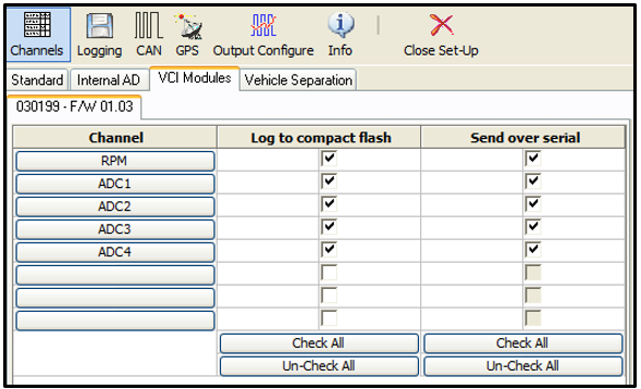
The MICIN01 can be connected to a VBOX via an RLCAB090-C cable. The user is required to load the MICIN01.DBC file on the VCI Modules tab, and then click a blank channel bar under the channels column to select one of the Micro Input Module’s data channels. Once the channels are loaded, the user can then individually choose specific channels they wish to log and, or send over the serial bus.
Please note, the micro input module is only compatible with VBOX’s with VCI capability.

Configuring an input channel
To configure a channel, click the corresponding channel button. A channel setup window will appear showing the current settings.
The Channel Name and Units can be changed for each of the input channels and a scale, offset, minimum and maximum can be applied to selected input channels. Edit the Name, units, scale, offset, minimum and maximum, then click the Apply button for the changes to be saved.
Channel Name
The user can change the channel name to provide a meaningful description for the input channel.
Units
The ‘Units’ option does not alter the recorded data. It is only a description for the user to understand the format of the data. The value of the data is only affected by the scale and offset values.
Scale
The scale value corresponds to M in the equation Y = MX + C that is applied to the input signal.
Offset
The offset value corresponds to C in the equation Y = MX + C.
Minimum
The minimum value the data is capable of displaying.
Maximum
The maximum value the data is capable of displaying.
