06 - MICIN Calculating Scale and Offset
When reading data from a vehicle using sensor equipment such as the Micro-Input Module it is often necessary to convert the data into a more meaningful format, for example converting a voltage from a throttle or brake pedal into something more useful like percentage pedal press.
Scale and Offset Calculator
- There is an online scale and offset calculator on our VBOX Motorsport website which can be used to quickly calculate the required scale and offset for analogue inputs. This can be found here.
- A scale and offset calculator is also available within the VBOX Video HD2 Setup Software, for use when configuring analogue inputs with a VBOX Video HD2 scene. More information on this is available here.
Typical RPM Scales
Typically an RPM signal from an ignition coil will need to be scaled to get an RPM in the form:
RPM = f *60* 2/cylinders.
This is because Input Modules gives pulses per second which we need to convert into revolutions per minute.
E.G. 1 pulse per second = 60 pulses per minute x 2 (2 revolutions of crankshaft per combustion of spark plug) = 120 divided by the number of cylinders (4) = revs per minute (30).
So, for a four cylinder engine it would be 120 divided by 4 = 30.
Try these values as starting points.
| Cylinders | Scale |
|---|---|
| 3 | 40 |
| 4 | 30 |
| 5 | 24 |
| 6 | 20 |
| 8 | 15 |
| 10 | 12 |
| 12 | 10 |
Calculating Scale and Offset Manually
This application note will explain step-by-step how to calculate the scale and offset values required to convert the throttle position voltage from the input of a Micro-Input Module to percentage throttle applied.
It should be noted that this calculation only works for linear data where the plot of the data produces a straight line.
1. Obtain Full Scale Voltage Values
Assume that the voltage read by the MCIN is 0.5 V when the pedal is not being pressed and 5 V when the pedal is fully pressed. You have two values which correspond to 0 % and 100 % throttle pedal position. So how do we determine what scale and offset values to apply to a voltage value to obtain throttle position as a percent?
2. Visualising the Data
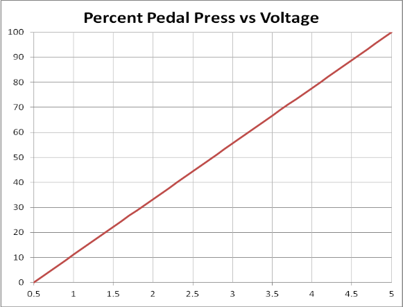
If you were to plot voltage (x) against percent (y), you have two sets of points that you can plot.
The line between these two points is a straight line.
| Voltage (x) | Pedal Press (y) |
|---|---|
| 0.5 | 0 % |
| 5 | 100 % |

3. The Equation Of a Straight Line
The equation describing a straight line is as follows:
Y = Mx + c
Where;
Y = The Y values (pedal press)
X = The X values (sensor voltage)
m = scale (gradient of the line)
c = offset (intercept with the Y-axis)
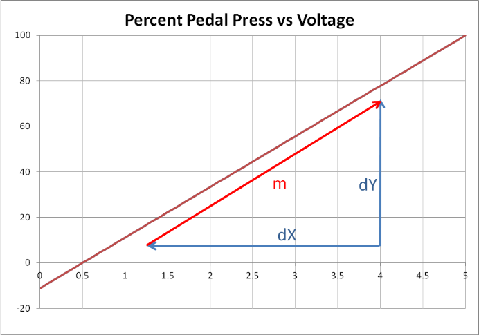
4. Calculating the Gradient of the Line
The gradient of a line is the change in Y divided by the change in X which gives:
m = dY/dX
dY = 100 – 0 = 100
dX = 5 – 0.5 = 4.5
Therefore the gradient of the line is:
dY/dX = (100 - 0)/(5 – 0.5)
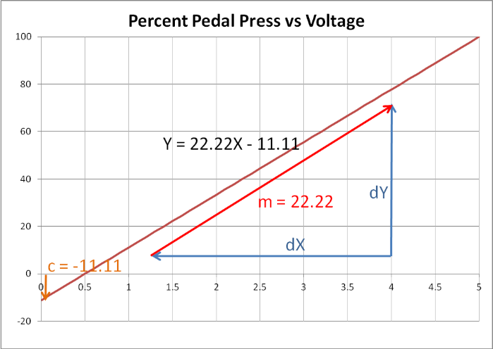
= 22.22

5. Substituting Values to Find the Offset
To find the offset value we simply substitute the known values back into our equation as follows:
Taking the values when the pedal is not pressed.
Voltage = 0.5 V, percent = 0.
Y = mX + c therefore 0 = (22.22 * 0.5) + c
0 = 11.11 + c
Taking 11.11 from both sides of the equation gives us:
C = -11.11
6. The Full Equation for the Line
Substituting these values back into the equation again gives us the full equation of the line which passes through our two points.
Y = 22.22X – 11.11
7. Checking the Equation
We can double check our equation is correct by calculating a percentage value for a known voltage output.
We know that:
| Voltage (x) | Percent Pedal Press (y) |
|---|---|
| 0.5 | 0 |
| 5 | 100 |
Using the equation we have just derived produces the following results:
Y = 22.22X – 11.11
Y = (22.22 * 0.5) – 11.11 = 0 %
This is correct, as 0.5 V is equal to a 0 % pedal press.
Y = (22.22 * 5.0) – 11.11 = 99.99 %
This is also correct as we know that 5 V = 100 % pedal press.
8. Plotting the Full Line
The graph below illustrates the calculated scale and offset values.

