Multi-Function Display App
The Multi-Function Display (MFD) app allows you to use the VBOX Touch as a display when connected to a VBOX 3i. It will show data from GPS derived channels that are output over CAN.
You can display up to 6 parameters on a single screen. Parameters such as speed, lateral and longitudinal acceleration, the radius of turn, distance travelled, heading and various brake test channels. It can also calculate and present performance test results, live from the test vehicle.
You can download the app here, and find instructions on how to install it here.
You will need the 'RLCAB005-C' cable to connect VBOX Touch to a VBOX 3i.
Getting Started
Connecting to VBOX 3i
You can connect VBOX Touch to VBOX 3i with the RLCAB005-C cable. Connect it to the Bottom CAN socket on the VBOX Touch and to the CAN port on the VBOX 3i. If you are using a CAN Hub, connect it to the Bottom CAN socket on the VBOX Touch and to the MFD port on the CAN Hub.
If you want to use VBOX Touch to run the MFD app as part of a daisy chain with a Racelogic module connected to VBOX 3i, you must connect VBOX Touch at the end of the daisy chain.
Power
When you are using the VBOX Touch with the MFD app, the unit is powered via its connection to the VBOX 3i. On boot up, the VBOX Touch will display a splash screen.
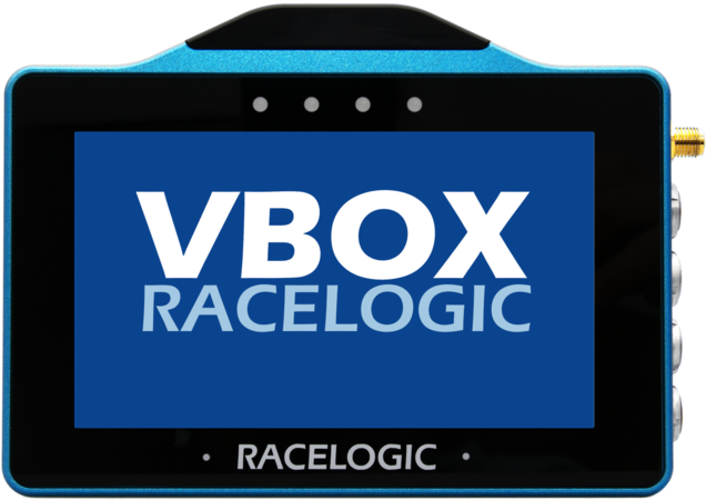
Splash Screen
The first time that the unit is booted up, the 1 Parameter screen will be presented. Every time after this, the last used screen will be opened (if an SD card is inserted).
SD Card
You can use an SD card to save and load settings, save test results, and update the firmware.
If you insert an SD card in the unit, the settings values will be remembered after each power cycle and the last used screen will be opened. If you do not have an SD card inserted in the unit, none of the settings will be remembered after a power cycle.
Screen Layout
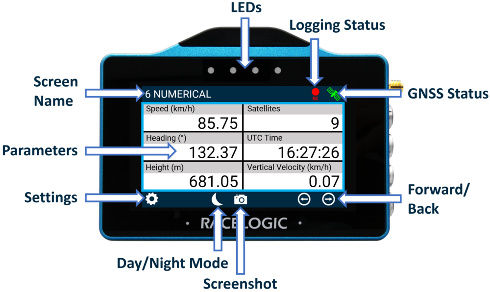
LEDs
Logging Status
Note: When using VBOX 3i units only
The Record icon shows the current logging status of the connected VBOX unit.
| When VBOX is logging data to the inserted CF card, the icon will be red. |  |
| When the unit is not logging data, the icon will be grey. |  |
When a CF card is detected and available within the VBOX (i.e. the CF Status icon is green), logging can also be controlled by pressing the Record Icon. If 'Logging Beep' is enabled in the General Settings menu, the unit will make an audible alert signal when the logging state of the connected VBOX unit changes.
If the grey Record Icon is pressed when the VBOX has its log mode set to ‘Log when moving’ and the vehicle is stationary, the screen title will be briefly display an 'ARMED' status. This indicates that the recording media has been detected, and the unit is waiting for starting conditions to be met before logging commences. When logging commences, the Record Icon will display as red.
If you press the grey Record icon when the unit is not detecting a CF card or if the media is full (i.e. the CF Status icon is red), the unit will emit an audible beep and display one of the following messages:
- NO MEDIA AVAILABLE - No detected recordable media.
- CARD FULL - Media detected but no logging capacity remains.
- NO MEDIA AVAILABLE - VBOX 3i is unable to write to recordable media (i.e. corrupt card).
If MFD Touch cannot detect a VBOX unit, it will display a 'NO CAN' message in this area. A Logging Status channel is also available for selection as a text parameter which will describe the current logging status of the connected VBOX.
GNSS Status
The Satellite icon displays the current GNSS status of the connected VBOX unit.
 |
Flashing Red No satellite lock/ IMU Coast (Solution Types 0 or 6) |
 |
Solid Green Standalone positional accuracy/ SBAS and Base Station DGPS corrections (Solution Types 1 or 2) |
 |
Solid Orange RTK Float (Solution Type 3) |
 |
Solid Purple RTK Fixed (Solution Type 4). |
 |
Solid White Robot Position, local co-ordinates (Solution Type 5) |
 |
If there is a valid dual antenna lock, a superscript '2' will appear next to the relevant GNSS status icon. |
| NO CAN | If it cannot detect a VBOX unit, you will see a 'NO CAN' message displayed in this area. |
Screen Name
This header shows the name of the current parameter screen. This can be changed by either pressing and holding or double-tapping the existing screen name, more information on this is available below.
Parameters
This area will display defined parameters dependent on which screen you are currently on, information on how to configure these can be found here.
Settings Button
The Settings button will open a Settings area that contains the VBOX Display and Decel Test Settings, along with the ability to save and load settings.
Forward/Back Buttons
| You can use the Forward and Back arrow buttons to navigate through the different parameter screens. You can also swipe left or right on the screen. |   |
Day/Night Mode Button
Tapping the Moon Icon on the bottom of any screen will enable Night Mode, and the colour scheme will invert to suit night-time operation.
Night Mode example
Alternatively, when in Night Mode, you can tap the Moon Icon on the bottom of any screen to revert back to Day Mode.
Note: Enabling Night Mode will reset any User Defined Text Colours.
Screenshot
|
Selecting the Screenshot button will save an image of what you see displayed on the screen to the inserted SD card. If the screenshot saves successfully, the LEDs will illuminate yellow in sequence from left to right (the progress of writing to the SD card). You will hear an audible confirmation notification when the screen capture is complete. If you were unsuccessful in saving the screenshot (if you did not insert an SD card or the card was full), you see 'NO SD CARD' appear at the top of the screen. The LEDs will flash red 2 times and you will hear an audible error notification. A captured image is saved as a 1.5 MB bitmap image, orientated at 90° to the original screen image, with the prefix 'screenshot'. |
 |
IMPORTANT
NEVER remove the SD card while you capture a screenshot with the unit, as it could cause it to crash!
Data Display
Adding/Removing Screens
The MFD app can display up to 6 defined VBOX 3i parameters. 8 different screen types are available, displaying a varying amount of parameters and gauges. You can add a maximum of 10 screens.
When the unit is booted up for the first time, the 6 Parameter screen will be presented by default. If you would like to add more screens, press the Forward arrow at the bottom right of the screen or swipe left to access the Add/Remove screen. The Add/Remove screen is always located after the last display screen.
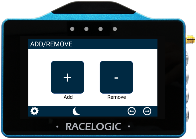
To Add a new screen, press the Add button. This will open up the Add Page selection screen where you can choose which display you would like. Swipe the screen left or right, or use the Forward or Back arrows on the sides of the screen to navigate through the available screens: 1 NUMERICAL, 3 NUMERICAL, 4 NUMERICAL, 6 NUMERICAL, ANALOGUE GAUGE, G-BALL, TARGET or BAR GRAPH.
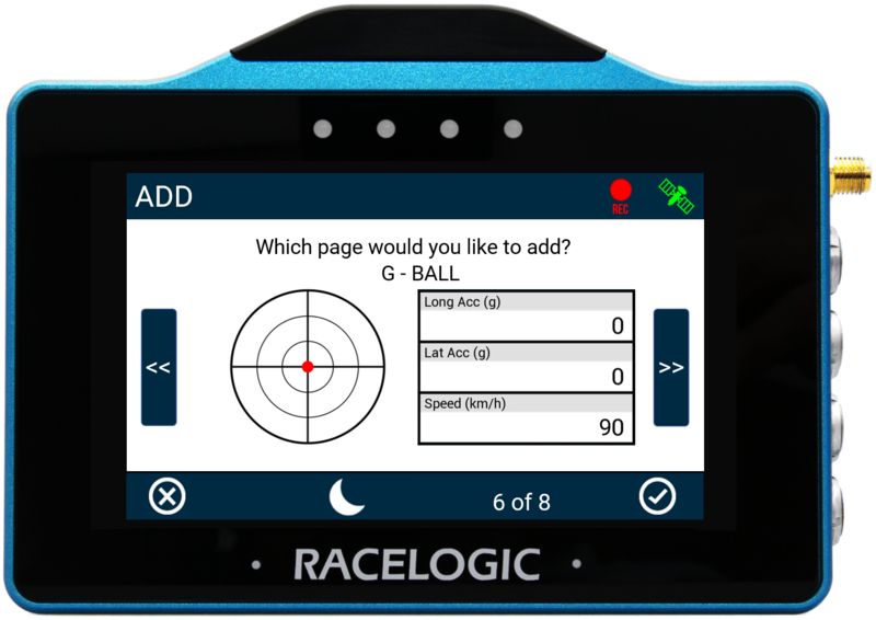
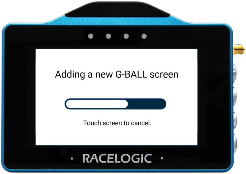
To add the screen, press the Confirm button at the bottom right of the screen, or press the Cancel button at the bottom left of the screen to return the Add/Remove screen without saving. If confirmed, a progress screen will be displayed along with a countdown. If you would like to cancel the addition of the screen, press the screen before the countdown runs out.
To remove a screen, press the Remove button from the Add/Remove screen, select the screen by Swiping left or right, or by using the Forward or Back arrows on the sides of the screen. Press the Confirm button at the bottom right of the screen to remove it.
Display Screens
When you have finished adding screens, you can change the display by selecting the Forward or Back arrows at the bottom right of the screen or by swiping left or right. You can find more information on the different screens by clicking on the respective images.
 1 Numerical Screen |
 3 Numerical Screen |
 4 Numerical Screen |
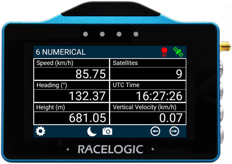
 6 Numerical Screen |
 Analogue Gauge Screen |
 G-Ball Screen |
 Target Screen |
 Bar Graph Screen |
Change Screen Name
You can change the name of each parameter screen by either pressing and holding or double-tapping the existing screen name at the top of the display. Use the presented keypad to enter the new screen name.
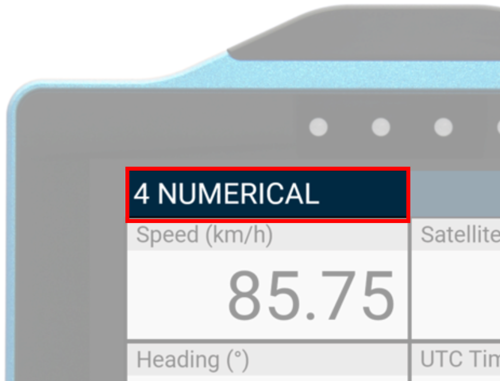 Existing Screen Name |
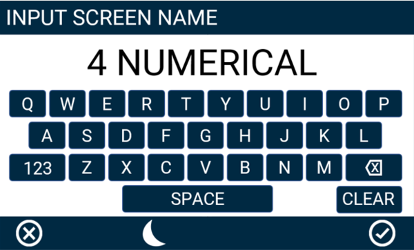 Screen Name Keypad Example |
To save the name inputted, press the Confirm button at the bottom right of the screen, or press the Cancel button at the bottom left of the screen to return the parameter screen without saving. If you have inserted an SD card, the unit will remember the value after each power cycle.
Configure a Parameter
You can configure each parameter by either pressing and holding or double-tapping the existing parameter area. This will open up the screen-specific menus.
Numerical Screens
Screens Overview
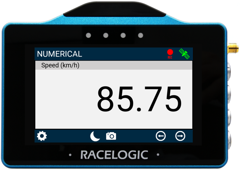
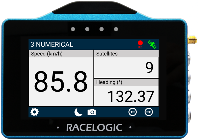
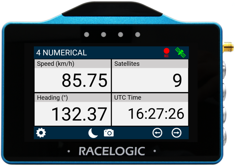
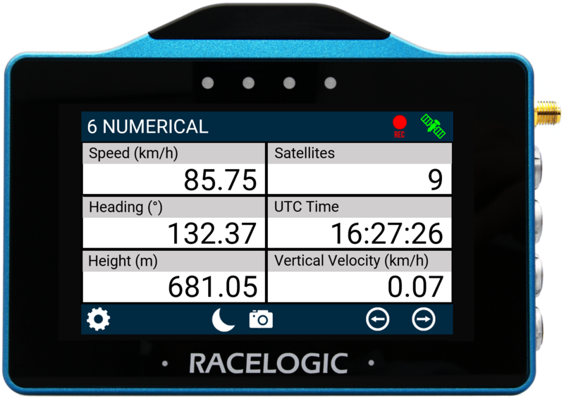
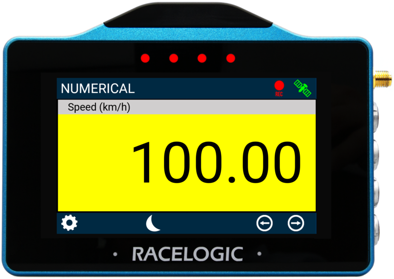
There are 4 screens available. You can display either 1, 3, 4 or 6 parameters. The first time that the unit is booted up, the 6 Parameter screen will be presented by default. Units used are dependent on what is selected within the Settings menu.
1 parameter screen |
3 parameter screen |
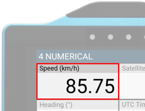
4 parameter screen |
6 parameter screen |
Default parameters:
- Numerical screen: Speed.
- 3 Numerical screen: Speed, Satellites and Heading.
- 4 Numerical screen: Speed, Satellites, Heading and UTC Time.
- 6 Numerical screen: Speed, Satellites, Heading, UTC Time, Height and Vertical Velocity.
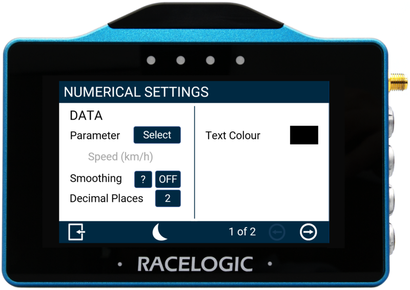
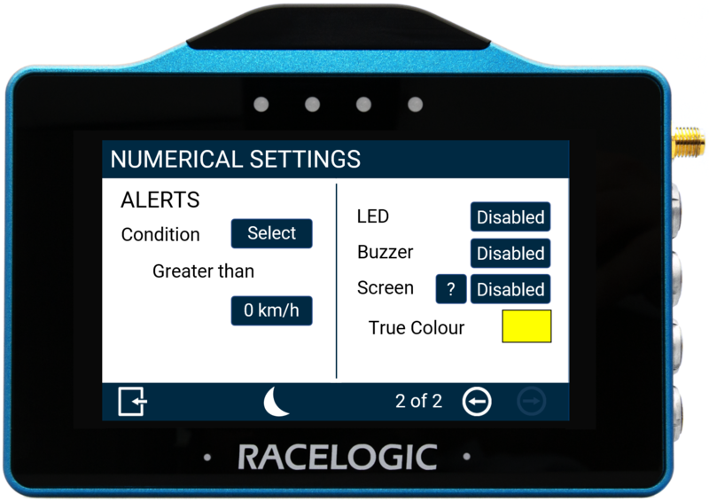
Numerical Settings
You can configure each parameter by either pressing and holding or double-tapping the existing parameter area. This will open up the Numerical Settings menus.
 Screen 1 |
 Screen 2 |
There are 2 numerical settings screens available: Data and Alerts, accessed by selecting the Forward or Back arrows at the bottom right of the screen or by swiping left or right. You can change the settings by pressing the corresponding button to each option.
Return to the parameter screen by pressing the Exit button at the bottom left.
Note: If you have inserted an SD card, the setting values will be remembered after each power cycle.
Data
Parameter
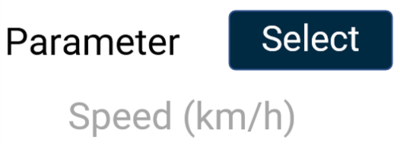
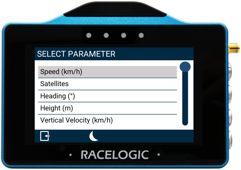
You can change a parameter by pressing the Select button to open the Data Source menu where you can choose from Standard and Decel test parameters. You can assign any data parameter that is available from the connected VBOX unit along with any calculated test results from the MFD app to the selected numerical element.
Note: The currently selected parameter is displayed in grey beneath the option.
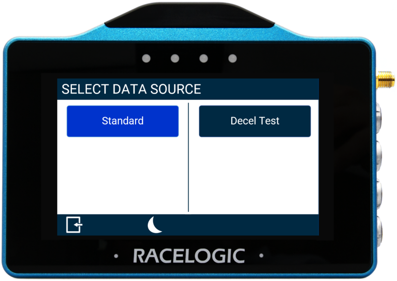 Data Source Menu |
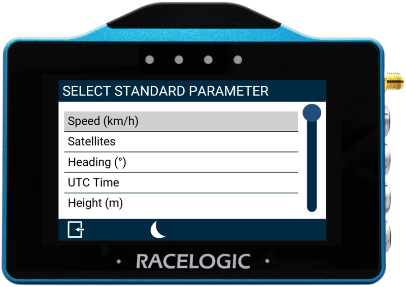 Standard Parameter Menu |
Use the scroll bar on the right-hand side of the selection screen to navigate through the options and press the desired parameter to confirm.
To return to the settings screen without saving, select the Exit button at the bottom left.
You can find a list of the available parameters here.
Smoothing

You can smooth the displayed live speed values if required. The input value determines the number of previous data samples used to smooth the displayed data. It does not affect any of the performance results or the logged data of the connected unit.
To enable smoothing, press the current value (off by default) and use the presented keypad to enter the number of previous data samples you would like to use in the display smoothing.
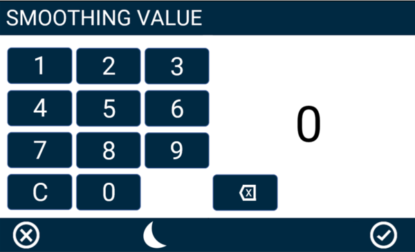
Smoothing Value Keypad Example
Save the selected value by pressing the Confirm button in the bottom right corner. Press the Cancel button in the bottom left corner to return to the Settings screen without saving.
Notes:
- The maximum input value is 99.
- Smoothing can introduce a slight delay to the displayed value.
- The setting will be greyed out and disabled if the numerical parameter being configured is UTC Time, Longitude, or Latitude.
Decimal Places
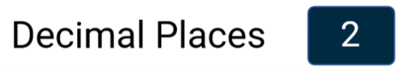
You can select how many decimal places are used to represent the nominated data for the selected numerical element.
Available options include 0, 1, 2 and 3. The default setting is 2. The exception is integer-only channels, including Satellites, Trigger Test Number, Decel Test Number, and UTC Time, which do not have any decimal points. Tap the buttons to change the decimal places used.
Text Colour

You can define the text colour of the numerical element data. Press the current colour (black by default) and use the presented RGB sliders to define the new colour. The area to the left of the sliders provides a colour preview.
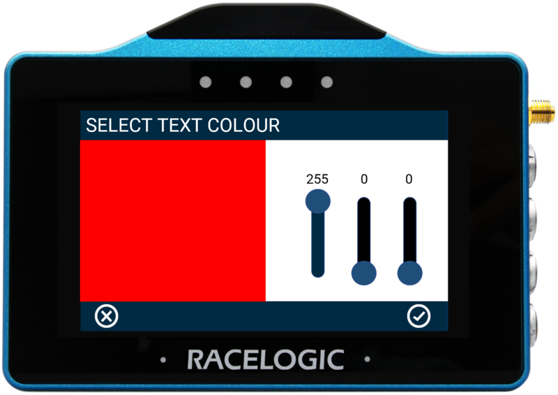 Text Colour Configuration Example |
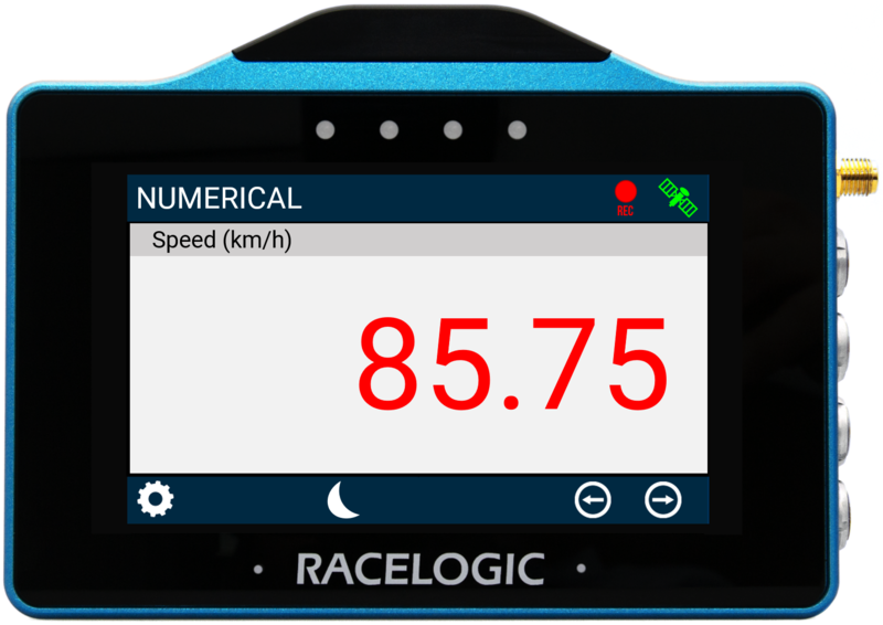 Text Colour Change Example |
To save the colour, press the Confirm button at the bottom right of the screen, or press the Cancel button at the bottom left of the screen to return the Settings screen without saving.
Notes:
- Changing the text colour applies to the data text only, it does not apply to the parameter label.
- If you enable Night Mode, all user-defined text colours will be reset.
Alerts
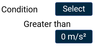
Condition
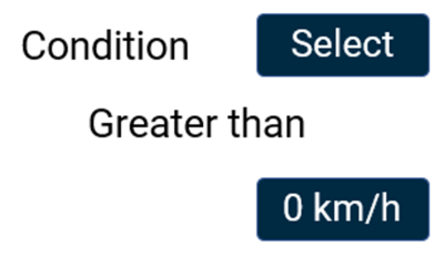
This option allows you to define an alert condition. Press the Select button to cycle through the available conditions: Equal To, Not Equal To, Less Than, Less Than or Equal To, Greater Than (default), Greater Than or Equal To, Between, or Not Between. You can then define the alert condition value(s) by pressing the value box and using the presented keypad.
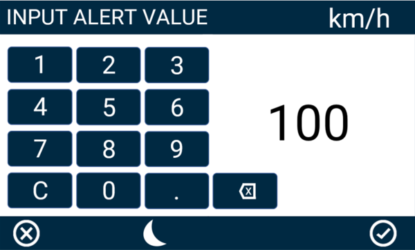
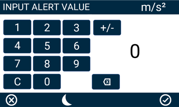
Alert Value Keypad Example
Save the selected value by pressing the Confirm button  in the bottom right corner. Press the Cancel button
  in the bottom left corner to return to the Settings screen without saving.
Note: The setting will be greyed out and disabled if the numerical parameter being configured is UTC Time, Longitude, or Latitude.
LED

Select this option to enable a solid or flashing visual alert when the Defined Alert Condition is met. Press the button to cycle through the options, the device will preview the setting with the 4 red LEDs across the top of the unit.
Note: The setting will be greyed out and disabled if the numerical parameter you are configuring is UTC Time, Longitude or Latitude.
Buzzer

Select this option to enable a sound alert when the Defined Alert Condition is met. The unit will beep when this is enabled.
Note: The setting will be greyed out and disabled if the numerical parameter you are configuring is UTC Time, Longitude or Latitude.
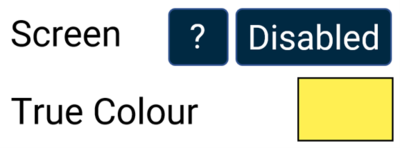
Screen
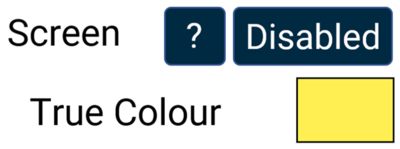
It is possible to enable a screen alert when the Defined Alert Condition is met. Once the value is achieved, the background of the parameter will change colour.
Note: The setting will be greyed out and disabled if the numerical parameter being configured is UTC Time, Longitude or Latitude.
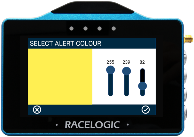
To change the background alert colour, press the current colour (yellow by default) and use the presented RGB sliders to define the required colour. The area to the left of the sliders provides a colour preview.
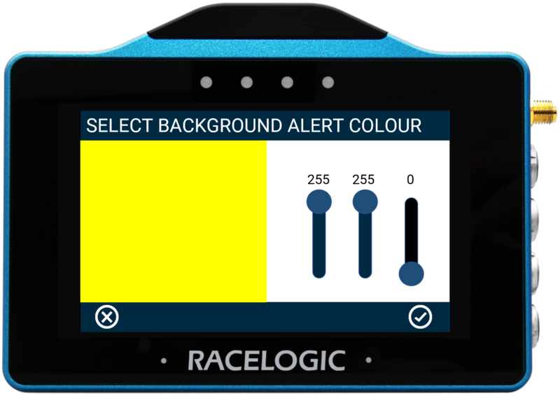 Screen Alert Colour Configuration Example |
 Screen Alert Example |
To save the colour, press the Confirm Button on the bottom right of the screen, or press the Cancel Button on the bottom left of the screen to return the Settings screen without saving.
Note: If you enable Night Mode, this will reset a user defined alert colour.
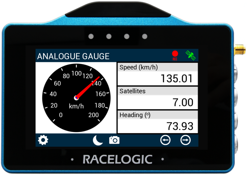
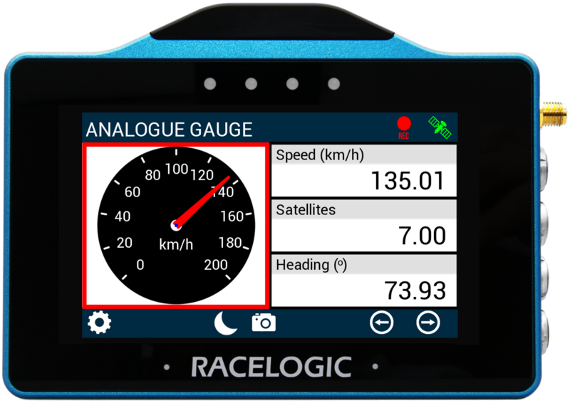
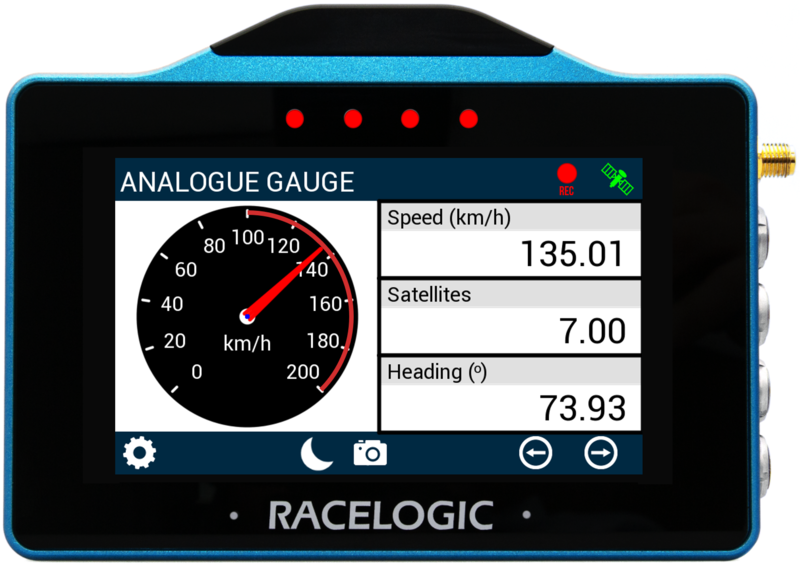
Analogue Gauge Screen
The Analogue Gauge screen contains an analogue needle gauge with 3 supporting numerical elements. Units used are dependent on what is selected within the Settings menu.
Analogue Gauge Element
The analogue needle gauge element is located on the left hand side of the screen, it provides a visual representation of a selected parameter (speed by default).
The gauge can be configured by either pressing and holding or double tapping on it. This will open up the Analogue Gauge Settings menus.
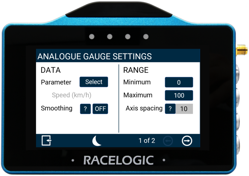 Screen 1 |
 Screen 2 |
There are 2 Analogue Gauge settings screens available: Data/Range and Alerts, accessed by selecting the Forward or Back arrows on the bottom right of the screen or by swiping the screen left or right. Settings can be changed by pressing on the corresponding button next to an option.
To return to the parameter screen, select the Exit Button on the bottom left.
Note: If an SD card is inserted, settings values will be remembered after each power cycle.
Data
Parameter
The gauge parameter is set as Speed by default, but can be changed by pressing the Select button to open the parameter list. You can assign any data parameter that is available from the connected VBOX to the Analogue Gauge (apart from UTC Time, Longitude or Latitude).
Note: The currently selected parameter is displayed in grey beneath the option.
Use the scroll bar on the right hand side of the selection screen to navigate through the options and press the desired parameter to confirm.
To return to the settings screen without saving, select the Exit Button on the bottom left.
A list of available parameters is available here.
Smoothing
If it is required, you can smooth the Analogue Gauge data. The input value determines the number of previous data samples used to smooth the displayed data. It does not affect any of the performance results or the logged data from the connected unit.
You can enable smoothing by pressing the current value (off by default) and using the keypad presented to enter the number of previous data samples you would like to use in the display smoothing.
Smoothing Value Keypad Example
Save the chosen value by pressing the Confirm button in the bottom right-hand corner. You can press the Cancel button in the bottom left-hand corner to return to the Settings screen without saving.
Notes:
- The maximum input value is 99.
- Smoothing can introduce a slight delay to the displayed value.
Range
Minimum/Maximum
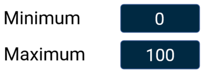
Define the minimum and maximum range values for the Analogue Gauge element's axes. Press the value boxes and use the presented keypads to define the required values (set as 0 and 100 by default).
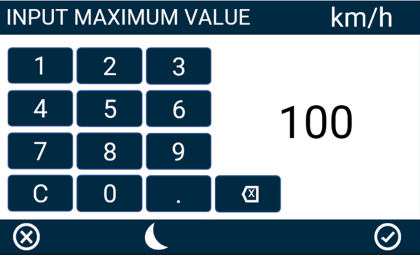
Maximum Range Keypad Example
Save the chosen value by pressing the Confirm button in the bottom right-hand corner. You can press the Cancel button in the bottom left-hand corner to return to the Settings screen without saving.
Notes:
- The maximum input value is 99999.
- The minimum input value is -99999 (when the signed parameter is selected, otherwise 0).
- One decimal place resolution available.
Axis Spacing
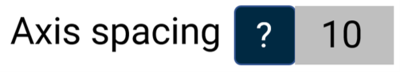
The Axis Spacing value tells you how much spacing there is between each gauge increment marker, the value changes dependent on the Minimum/Maximum Range Value.
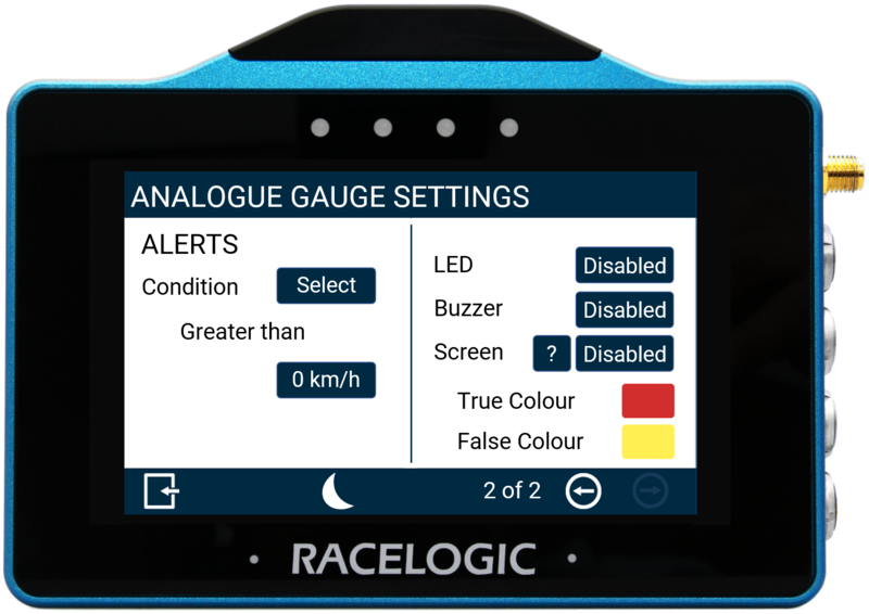
Alerts
Condition
This option allows you to define an alert condition. Press the Select button to cycle through the available conditions: Equal To, Not Equal To, Less Than, Less Than or Equal To, Greater Than (default), Greater Than or Equal To, Between, or Not Between. You can then define the alert condition value(s) by pressing the value box and using the presented keypad.
Alert Value Keypad Example
Save the chosen value by pressing the Confirm button in the bottom right-hand corner. You can press the Cancel button in the bottom left-hand corner to return to the Settings screen without saving.
LED
Select to enable a solid or flashing visual alert when the Defined Alert Condition is met. Press the button to cycle through the options, the device will preview the setting with the 4 red LEDs across the top of the unit.
Buzzer
Select to enable a sound alert when the Defined Alert Condition is met. The unit will beep when enabled.
Screen
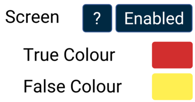
It is possible to enable a screen target zone in relation to the Defined Alert Condition. If the value has yet to be achieved, the 'False Colour' will appear within the target zone, once the value is achieved, the 'True Colour' will appear within the target zone.
To change the True and False target zone alert colours, press the current colours (yellow and red by default) and use the presented RGB sliders to define the required colours. The area to the left of the sliders provides a colour preview.
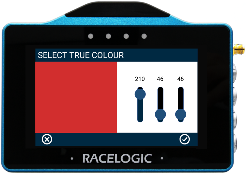 True Colour Configuration Example |
 Screen Alert Example |
To save a colour, press the Confirm Button on the bottom right of the screen, or press the Cancel Button on the bottom left of the screen to return the Settings screen without saving.
Numerical Elements
The 3 numerical elements are located on the right hand side of the screen and include Speed, Satellites and Heading parameters by default.
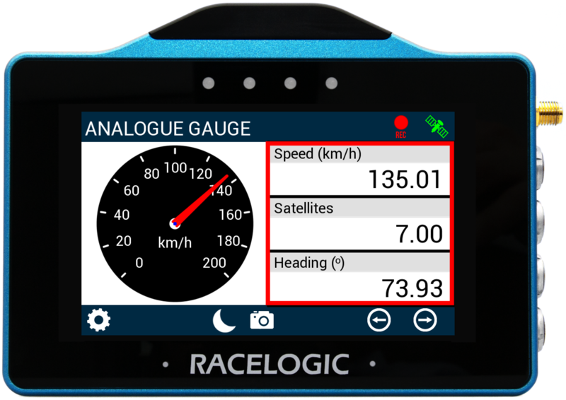
Each parameter can be configured by either pressing and holding or double tapping the existing parameter area. This will open up the Numerical Settings menus where you can define the parameter.
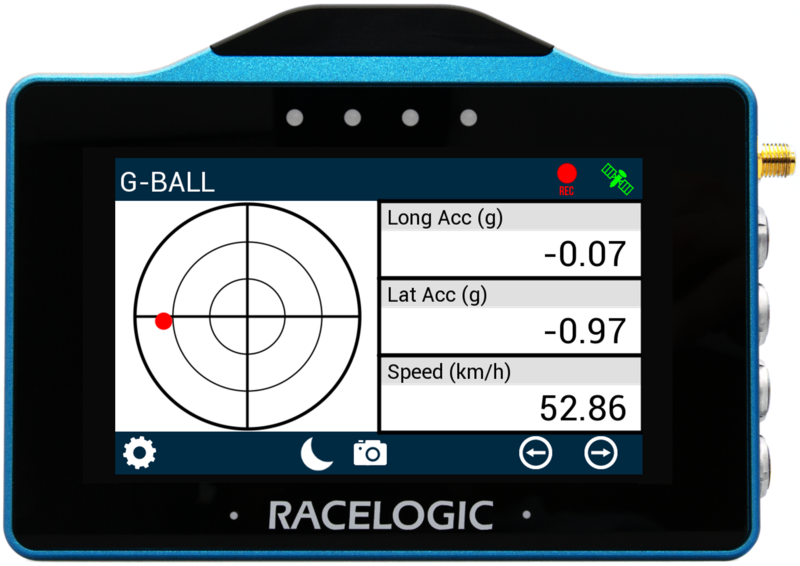
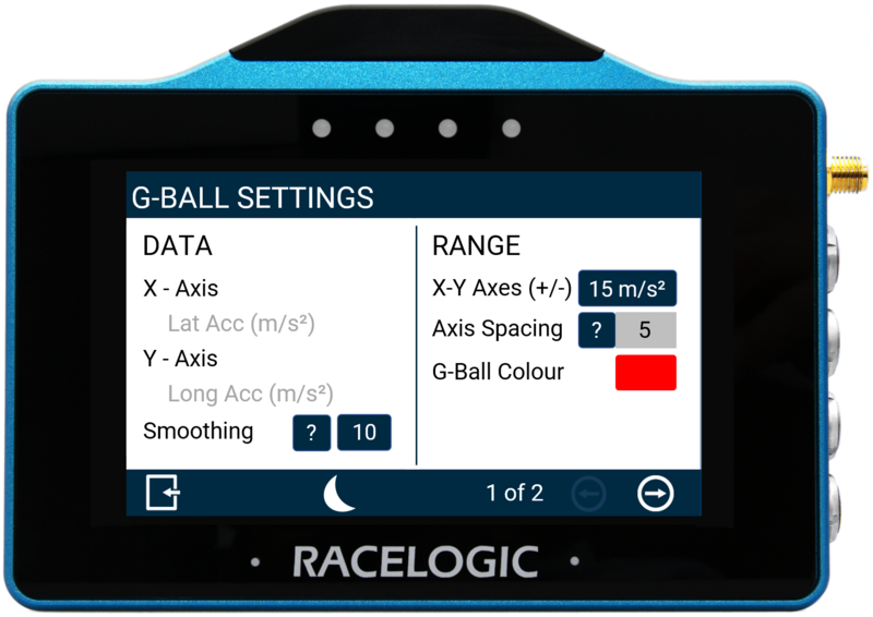
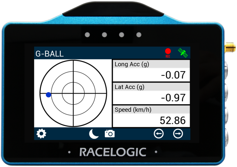
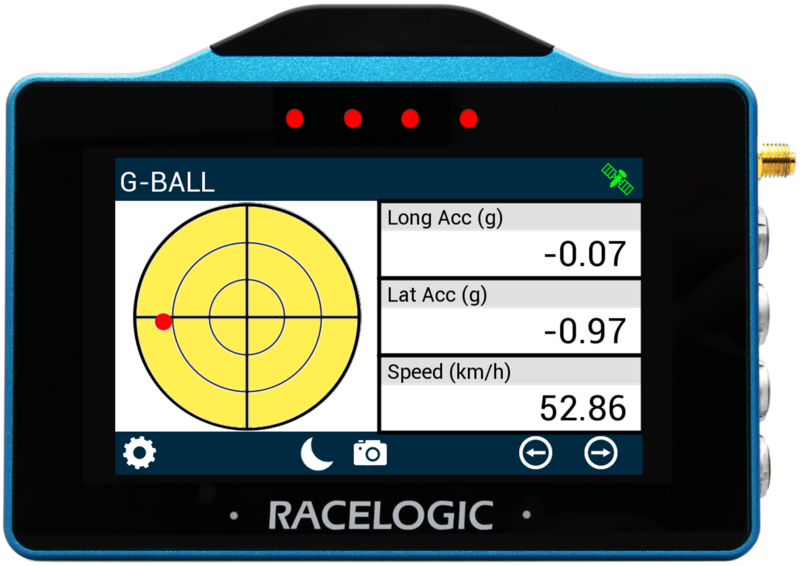
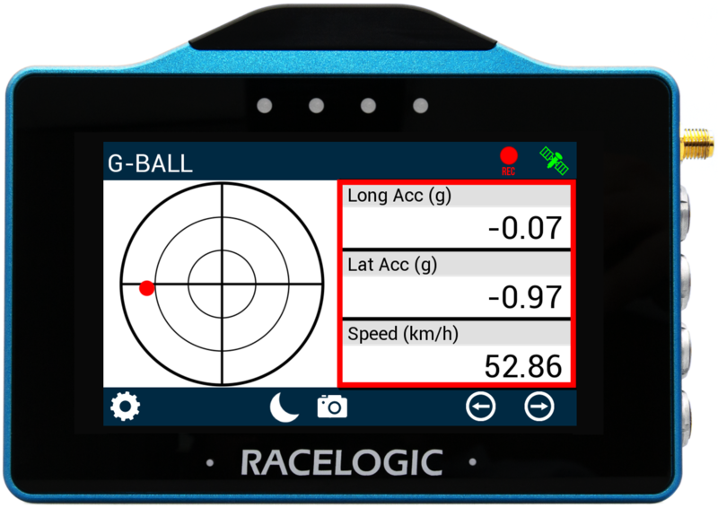
G-Ball Screen
The G-Ball screen contains a G-Ball gauge with 3 supporting numerical elements. Units used are dependent on what is selected within the Settings menu.
G-Ball Element
The G-Ball element is located on the left hand side of the screen, it provides a visual representation of the longitudinal and lateral acceleration parameters.

The gauge can be configured by either pressing and holding or double tapping on it. This will open up the G-Ball Settings menus.
 Screen 1 |
 Screen 2 |
There are 2 G-Ball settings screens available: Data / Range and Alerts, accessed by selecting the Forward or Back arrows on the bottom right of the screen or by swiping the screen left or right. Settings can be changed by pressing on the corresponding button next to an option.
To return to the parameter screen, select the Exit Button on the bottom left.
Note: If an SD card is inserted, settings values will be remembered after each power cycle.
Data
X/Y Axis
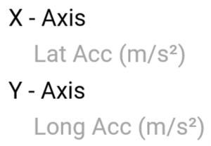
This area displays which acceleration parameters are associated with which G-Ball gauge axis (X-axis: lateral acceleration, Y-axis: longitudinal acceleration).
Smoothing

If you need it, you can smooth the G-Ball gauge data. The input value determines the number of previous data samples used to smooth the displayed gauge data. It does not affect any of the performance results or the logged data of the connected unit.
The SMOOTHING VALUE is set to 10 samples by default. You can change this value or turn off the smoothing by pressing the current value and using the presented keypad to enter the number of previous data samples you would like to use in the display smoothing.
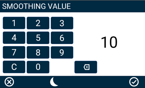
Smoothing Value Keypad Example
Save the chosen value by pressing the Confirm button in the bottom right-hand corner. You can press the Cancel button in the bottom left-hand corner to return to the Settings screen without saving.
Notes:
- The maximum input value is 99.
- Smoothing can introduce a slight delay to the displayed value.
Range
X-Y Axes (+/-)
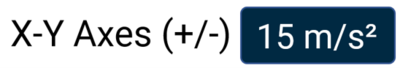
This option allows you to define an absolute range for the G-Ball element's axes. Press on the value box and use the presented keypad to define the required value.

X-Y Axis Range Keypad Example
Save the chosen value by pressing the Confirm button in the bottom right corner. Press the Cancel button in the bottom left corner of the screen to return to the Settings screen without saving.
Notes:
- The maximum input value is 999.
- The minimum input value is 0.1.
- One decimal place resolutions are available to values under 100.
Axis Spacing
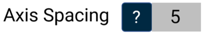
The Axis Spacing value tells you how much spacing there is between each gauge increment marker, the value changes dependent on the X-Y Axes Range Value.
G-Ball Colour

It is possible to define the colour of the G-Ball within the gauge. To change, press the current colour (red by default) and use the presented RGB sliders to define the required colour. The area to the left of the sliders provides a colour preview.
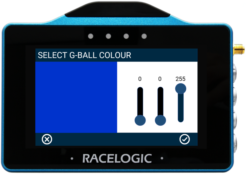 G-Ball Colour Configuration Example |
 G-Ball Colour Change Example |
To save the colour, press the Confirm Button on the bottom right of the screen, or press the Cancel Button on the bottom left of the screen to return the Settings screen without saving.
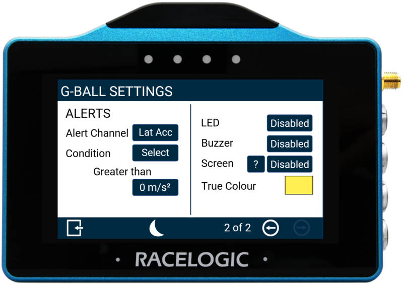
Alerts
Alert Channel

This option allows you to define an alert channel. Press the Select button to cycle between either lateral or longitudinal acceleration.
Condition
This option allows you to define an alert condition. Press the Select button to cycle through the available conditions: Equal To, Not Equal To, Less Than, Less Than or Equal To, Greater Than (default), Greater Than or Equal To, Between, or Not Between.
You can then define the alert condition value(s) by pressing the value box and using the presented keypad.
Alert Value Keypad Example
Save the chosen value by pressing the Confirm button in the bottom right corner. Press the Cancel button in the bottom left corner to return to the Settings screen without saving.
LED
Select to enable a solid or flashing visual alert when the Defined Alert Condition is met. Press the button to cycle through the options, the device will preview the setting with the 4 red LEDs across the top of the unit.
Buzzer
Select to enable a sound alert when the Defined Alert Condition is met. The unit will beep when enabled.
Screen
It is possible to enable a screen alert when the Defined Alert Condition is met. Once the value is achieved, the background of the parameter will change colour.
To change the background alert colour, press the current colour (yellow by default) and use the presented RGB sliders to define the required colour. The area to the left of the sliders provides a colour preview.
Screen Alert Colour Configuration Example |
 Screen Alert Example |
To save the colour, press the Confirm Button on the bottom right of the screen, or press the Cancel Button on the bottom left of the screen to return the Settings screen without saving.
Numerical Elements
The 3 numerical elements are located on the right hand side of the screen and include Longitudinal Acceleration, Lateral Acceleration and Speed parameters by default.
Each parameter can be configured by either pressing and holding or double tapping the existing parameter area. This will open up the Numerical Settings menus.
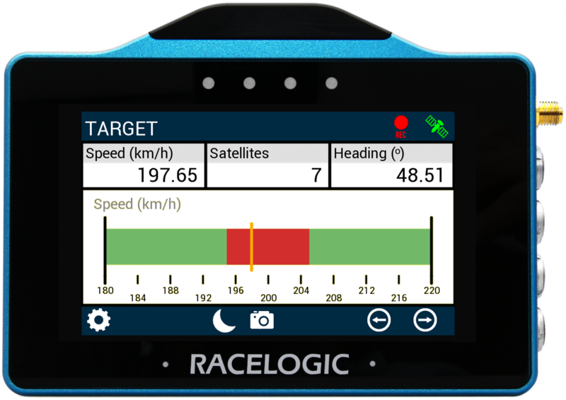
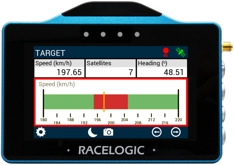
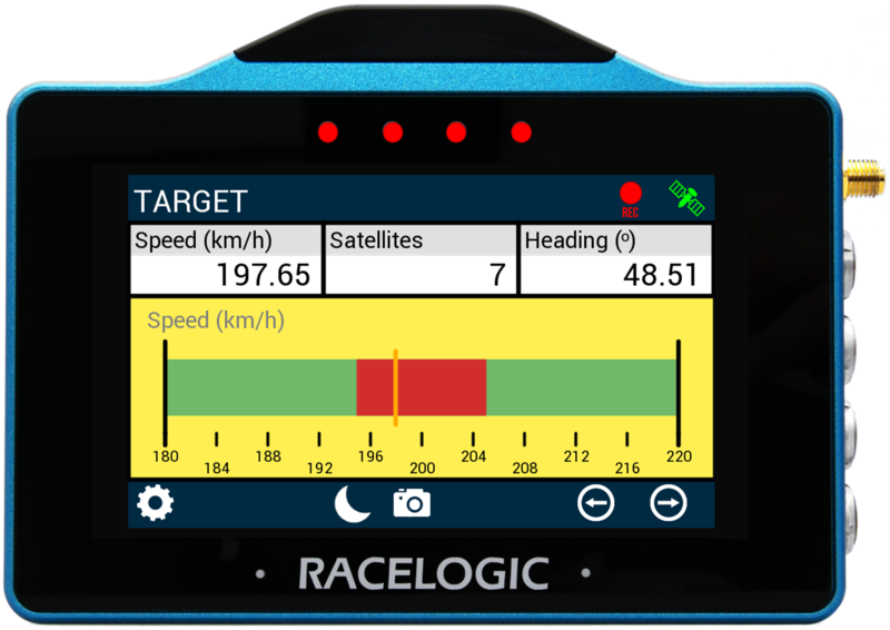
Target Screen
The Target screen contains a target gauge with 3 supporting numerical elements. Units used are dependent on what is selected within the Settings menu.
Target Element
The Target Graph gauge element is located on the bottom of the screen, it provides a visual representation of a selected parameter (speed by default).
The gauge can be configured by either pressing and holding or double tapping on it. This will open up the Target Graph Settings menus.
 Screen 1 |
 Screen 2 |
There are 2 Target Graph settings screens available: Data / Range and Colours / Alert, accessed by selecting the Forward or Back arrows on the bottom right of the screen or by swiping the screen left or right. Settings can be changed by pressing on the corresponding button next to an option.
To return to the parameter screen, select the Exit Button on the bottom left.
Note: If an SD card is inserted, settings values will be remembered after each power cycle.
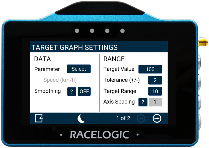
Data
Parameter
The gauge parameter is set as Speed by default, but can be changed by pressing the Select button to open the parameter list. You can assign any data parameter that is available from the connected VBOX to the Target Gauge (apart from UTC Time, Longitude or Latitude).
Note: The currently selected parameter is displayed in grey beneath the option.
Use the scroll bar on the right hand side of the selection screen to navigate through the options and press the desired parameter to confirm.
To return to the settings screen without saving, select the Exit Button on the bottom left.
A list of available parameters is available here.
Smoothing
You can smooth the Target data if required. The input value determines the number of previous data samples used to smooth the displayed data. It does not affect any of the performance results or the logged data of the connected unit.
To enable smoothing, press the current value (off by default) and use the presented keypad to enter the number of previous data samples you would like to use within the display smoothing.
Smoothing Value Keypad Example
Save your selected value by pressing the Confirm button in the bottom right corner. Press the Cancel button in the bottom left corner to return to the Settings screen without saving.
Notes:
- The maximum input value is 99.
- Smoothing can introduce a slight delay to the displayed value.
Range
Target Value

The target value will be located at the centre of the gauge. You can define this by pressing the value box and using the presented keypad to define the required value (set as 240 by default).
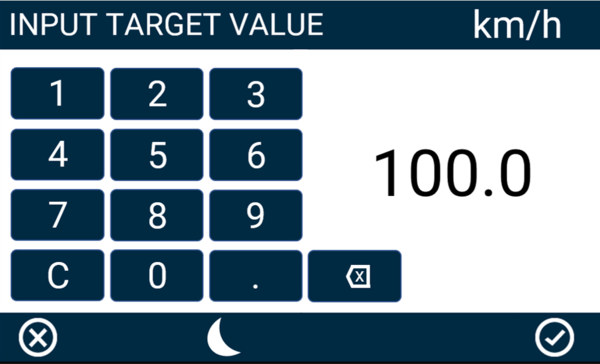
Target Value Keypad Example
Save your selected value by pressing the Confirm button in the bottom right corner. Press the Cancel button in the bottom left corner to return to the Settings screen without saving.
Notes:
- The maximum input value is 99999.
- The minimum input value is -99999 (when the signed parameter is selected, otherwise 0).
- One decimal place resolution is available to values under 10000.
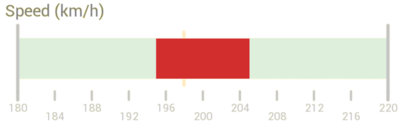
Tolerance (+/-)

Define the tolerance (target zone) displayed either side of the target value, the colour used for this zone (red by default) can be defined by pressing on the Target Zone option within the Colours Settings Area.
Press the value box and use the keypad presented to define the required value, set as 2 by default. Using the default +/- tolerance value of 2 as an example, for a target value of 100, the target zone would be from 98 – 102.
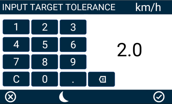
Target Tolerance Keypad Example
To save the value inputted, press the Confirm Button on the bottom right of the screen, or press the Cancel Button on the bottom left of the screen to return the Settings screen without saving.
Notes:
- The maximum input value is 9999.
- The minimum input value is 0.1.
- One decimal place resolution available to values under 1000.
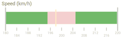
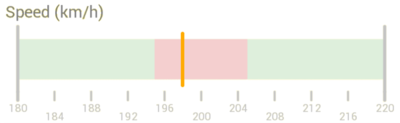
Target Range
Define the range of the background bar, the colour used for the bar (green by default) can be defined by pressing on the Bar option within the Colours Settings Area.
Press the value box and use the keypad presented to define the required value, set as 10 by default. Using the default range value of 10 as an example, for a target value of 100, the bar range would be from 95 – 105.
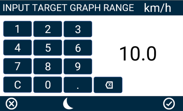
Target Range Keypad Example
To save the value inputted, press the Confirm Button on the bottom right of the screen, or press the Cancel Button on the bottom left of the screen to return the Settings screen without saving.
Notes:
- The maximum input value is 9999.
- The minimum input value is double the Target Value Tolerance setting.
- One decimal place resolution available to values under 1000.
Axis Spacing
The Axis Spacing value tells you how much spacing there is between each gauge increment marker, the value changes dependent on the Target Range Value.
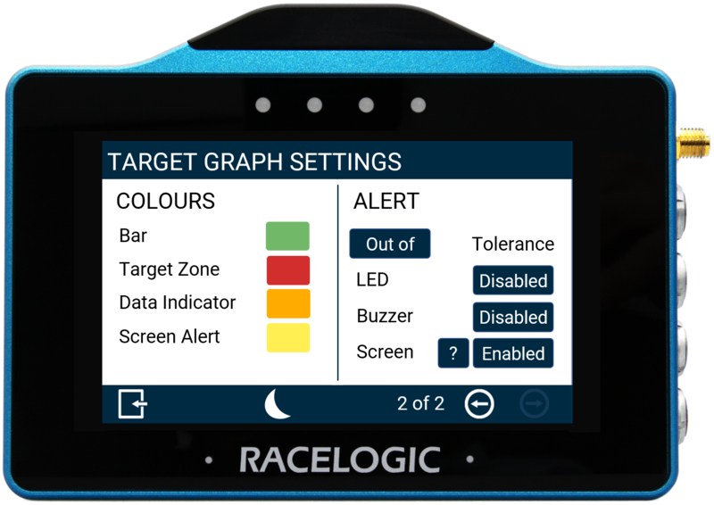
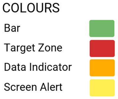
Colours
|
Bar: Set the colour of the background bar.
Target Zone: Set the colour of the Target Zone, which is configured using the Tolerance Value.
Data Indicator: Set the colour of the Data Indicator which is the current value.
Screen Alert: Set the colour of the Screen Alert. |
 |
To change any of the colours used, press the current colours and use the presented RGB sliders to define the required colours. The area to the left of the sliders provides a colour preview.
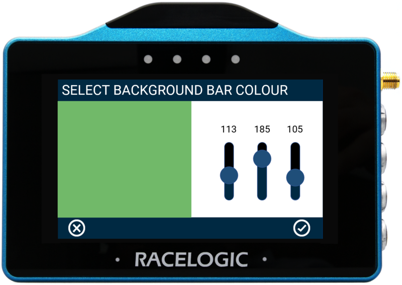
Background Bar Colour Configuration Example
To save a colour, press the Confirm Button on the bottom right of the screen, or press the Cancel Button on the bottom left of the screen to return the Settings screen without saving.
Note: If you enable Night Mode, this will reset any user defined colours.
Alert
Tolerance

This option allows you to define whether the alert is for a value Out of (default) or Within the Defined Target Value Tolerance. Press the button to change the option.
LED
Select to enable a solid or flashing visual alert when the Defined Target Value Tolerance is met. Press the button to cycle through the options, the device will preview the setting with the 4 red LEDs across the top of the unit.
Buzzer
Select to enable a sound alert when the Defined Target Value Tolerance is met. The unit will beep when enabled.
Screen
It is possible to enable a screen alert when the Defined Target Value Tolerance is met. Once the value is achieved, the background of the parameter will change colour.
Note: The setting will be greyed out and disabled if the numerical parameter being configured is UTC Time, Longitude or Latitude.
The background alert colour can be changed by pressing the current Screen Alert colour (yellow by default) within the Colours area and using the presented RGB sliders to define the required colour. The area to the left of the sliders provides a colour preview.
 Screen Alert Colour Configuration Example |
 Screen Alert Example |
To save a colour, press the Confirm Button on the bottom right of the screen, or press the Cancel Button on the bottom left of the screen to return the Settings screen without saving.
Note: If you enable Night Mode, this will reset any user defined alert colours.
Numerical Elements
The 3 numerical elements are located on the top of the screen and include Speed, Satellites and Heading parameters by default.
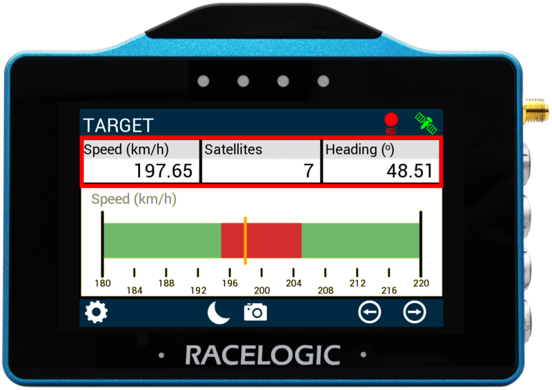
Each parameter can be configured by either pressing and holding or double tapping the existing parameter area. This will open up the Numerical Settings menus.
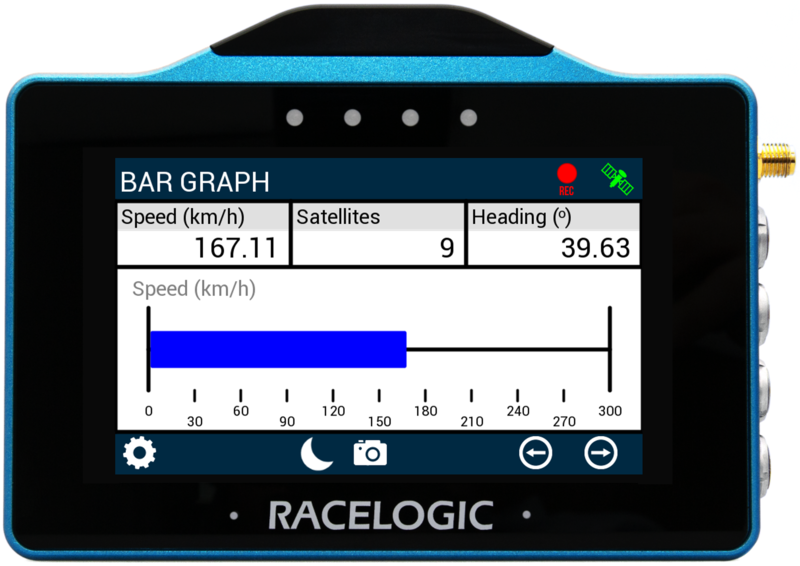
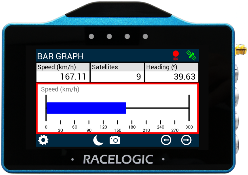
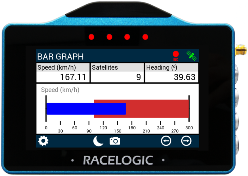
Bar Graph Screen
The Bar Graph screen contains a bar graph gauge with 3 supporting numerical elements. Units used are dependent on what is selected within the Settings menu.
>
Bar Graph Element
The Bar Graph gauge element is located on the bottom of the screen, it provides a visual representation of a selected parameter (speed by default).
The gauge can be configured by either pressing and holding or double tapping on it. This will open up the Bar Graph Settings menus.
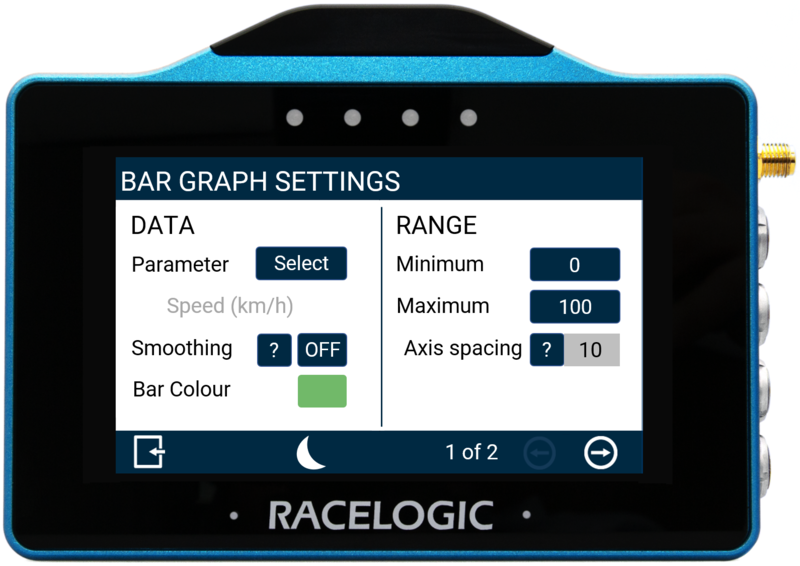 Screen 1 |
 Screen 2 |
There are 2 Bar Graph settings screens available: Data/Range and Alerts, accessed by selecting the Forward or Back arrows on the bottom right of the screen or by swiping the screen left or right. Settings can be changed by pressing on the corresponding button next to an option.
To return to the parameter screen, select the Exit Button on the bottom left.
Note: If an SD card is inserted, settings values will be remembered after each power cycle.
Data
Parameter
The gauge parameter is set as Speed by default but can be changed by pressing the Select button to open the parameter list. You can assign any data parameter that is available from the connected VBOX to the Bar Graph Gauge (apart from UTC Time, Longitude or Latitude).
Note: The currently selected parameter is displayed in grey beneath the option.
Use the scroll bar on the right hand side of the selection screen to navigate through the options and press the desired parameter to confirm.
To return to the settings screen without saving, select the Exit Button on the bottom left.
A list of available parameters is available here.
Smoothing
If required, you can have the Bar Graph data smoothed. The input value determines the number of previous data samples used to smooth the displayed data. It does not affect any of the performance results or the logged data of the connected unit.
To enable smoothing, press the current value (off by default) and use the presented keypad to enter the number of previous data samples you would like to use for the display smoothing.
Smoothing Value Keypad Example
Save your selected values by pressing the Confirm button in the bottom right corner of the screen. Press the Cancel button in the bottom left corner of the screen to return to the Settings screen without saving.
Notes:
- The maximum input value is 99.
- Smoothing can introduce a slight delay to the displayed value.
Bar Colour

To change the colour of the bar within the Bar Graph, press the current colour (green by default) and use the presented RGB sliders to define the required colour. The area to the left of the sliders provides a colour preview.
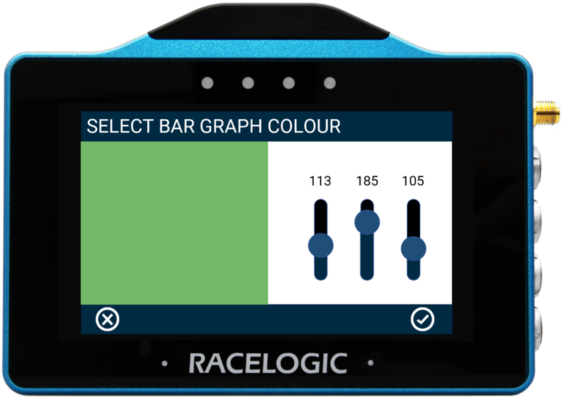
To save a colour, press the Confirm Button on the bottom right of the screen, or press the Cancel Button on the bottom left of the screen to return the Settings screen without saving.
Note: If you enable Night Mode, this will reset a user defined bar colour.
Range
Minimum/Maximum
Define the minimum and maximum range values for the Bar Graph element's axes. Press the value boxes and use the presented keypad to define the required values, set as 0 and 100 by default.
Maximum Range Keypad Example
Save your selected values by pressing the Confirm button in the bottom right corner of the screen. Press the Cancel button in the bottom left corner of the screen to return to the Settings screen without saving.
Notes:
- The maximum input value is 99999.
- The minimum input value is -99999 (when a signed parameter is selected, otherwise 0).
- One decimal place resolution available.
Axis Spacing
The Axis Spacing value tells you how much spacing there is between each gauge increment marker, the value changes dependent on the Minimum/Maximum Range Value.
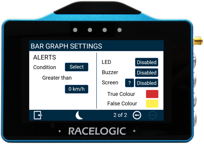
Alerts
Condition
This option allows you to define an alert condition. Press the Select button to cycle through the available conditions: Equal To, Not Equal To, Less Than, Less Than or Equal To, Greater Than (default), Greater Than or Equal To, Between, or Not Between. You can then define the alert condition value(s) by pressing the value box and using the presented keypad.
Alert Value Keypad Example
Save your selected values by pressing the Confirm button in the bottom right corner of the screen. Press the Cancel button in the bottom left corner of the screen to return to the Settings screen without saving.
Note: The setting will be greyed out and disabled if the configured numerical parameter is UTC Time, Longitude or Latitude.
LED
Select to enable a solid or flashing visual alert when the Defined Alert Condition is met. Press the button to cycle through the options, the device will preview the setting with the 4 red LEDs across the top of the unit.
Buzzer
Select to enable a sound alert when the Defined Alert Condition is met. The unit will beep when enabled.
Screen
It is possible to enable a screen target zone in relation to the Defined Alert Condition. If the value has yet to be achieved, the 'False Colour' will appear within the target zone, once the value is achieved, the 'True Colour' will appear within the target zone.
To change the True and False target zone alert colours, press the current colours (yellow and red by default) and use the presented RGB sliders to define the required colours. The area to the left of the sliders provides a colour preview.
True Colour Configuration Example |
 Screen Alert Example |
To save a colour, press the Confirm Button on the bottom right of the screen, or press the Cancel Button on the bottom left of the screen to return the Settings screen without saving.
Note: If you enable Night Mode, this will reset any user defined alert colours.
Numerical Elements
The 3 numerical elements are located on the top of the screen and include Speed, Satellites and Heading parameters by default.
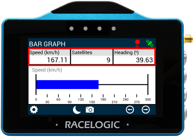
Each parameter can be configured by either pressing and holding or double tapping the existing parameter area. This will open up the Numerical Settings menus.
General Settings
The MFD app General Settings menus are available by selecting the Settings Button on the bottom left of the screen.
There are 2 Settings menus available: VBOX Display Settings and Decel Test Settings, along with options to Save and Load the settings. They can be accessed by pressing the desired option.
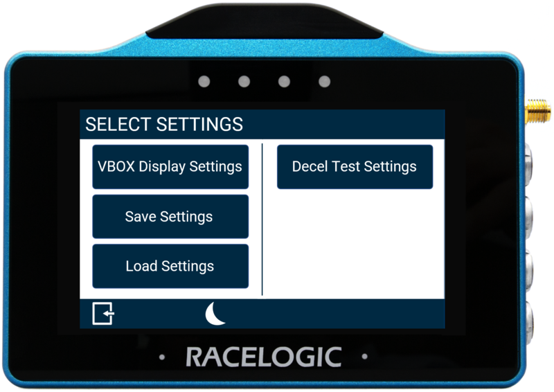
To return to the parameter screen, select the Exit Button on the bottom left.
Note: If an SD card is inserted, settings values will be remembered after each power cycle.
VBOX Display Settings
There are 3 Display Settings screens available, accessed by selecting the Forward or Back arrows on the bottom right of the screen or by swiping the screen left or right. Settings can be changed by pressing on the corresponding button next to an option.
To return to the main settings screen, select the Exit Button on the bottom left.
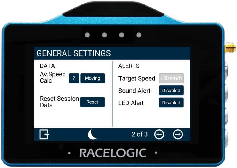
General Settings
These two menu screens contain units, brightness, average speed calculation, reset and alert options.
|
|
|
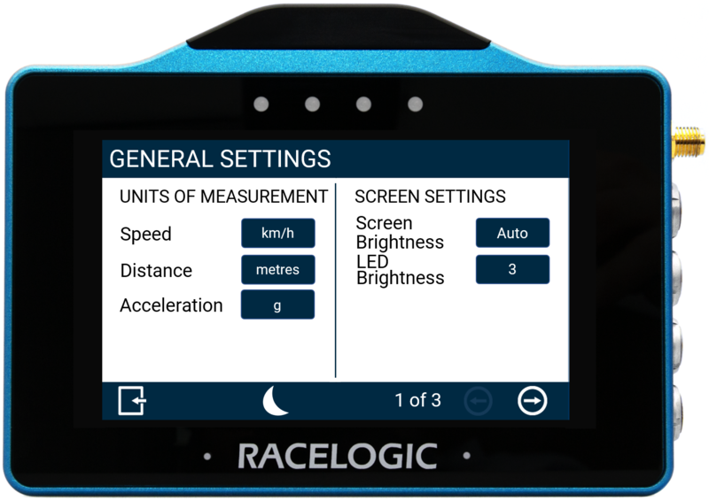
Units of Measurement
Speed
Distance
Acceleration
Screen Settings
Screen Brightness
LED Brightness
Data
Average Speed Calculation
Reset Session Data
Alerts
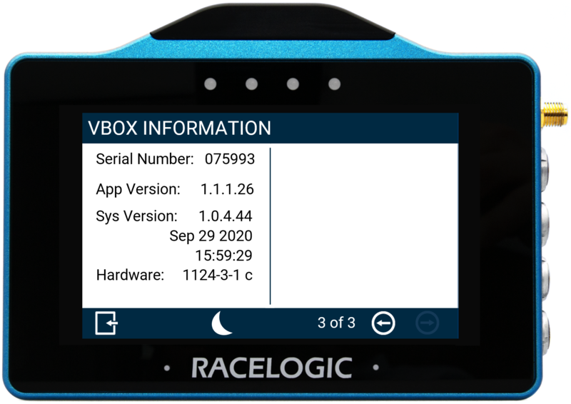
VBOX Information
The VBOX Information menu is the final screen within the Settings menu. It displays the device serial number, firmware version number and hardware version number. This information is useful in the event of troubleshooting a potential issue with the VBOX Touch device.
Decel Test Settings
There are 2 Decel Test Settings screens available, accessed by selecting the Forward or Back arrows on the bottom right of the screen or by swiping the screen left or right. Settings can be changed by pressing on the corresponding button next to an option.
To return to the main settings screen, select the Exit Button on the bottom left.
These two menu screens enable you to configure a deceleration test and contain start/end, alerts ad MFDD options.
Parameters for the test can be viewed on the display via the Decel Test parameters.
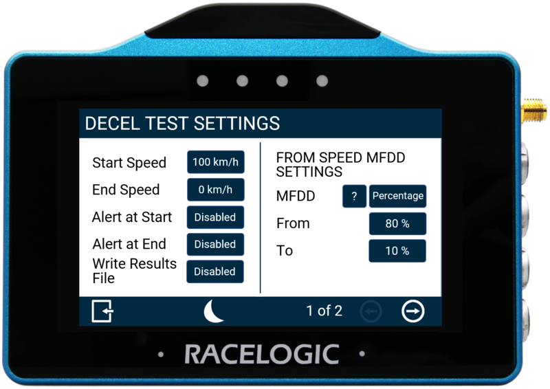 Screen 1 |
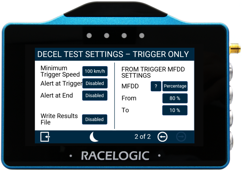 Screen 2 |
The first settings screen is for conducting deceleration tests using start and end speed values, the second screen is for when using a brake trigger.
Start/End Speed
Minimum Trigger Speed
Alert at Start
Alert at Trigger
Alert at End
Write Results File
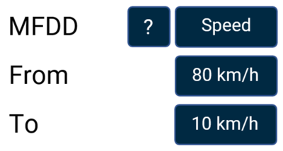
MFDD Settings
This area allows you to set up the start and end period of the MFDD (Mean Fully Developed Deceleration) analysis period.
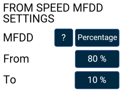 Speed MFDD Settings |
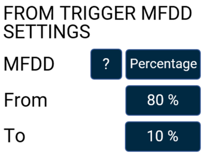 Trigger MFDD Settings |
This deceleration figure is used to show the maximum deceleration figure a vehicle can achieve. It is usually the deceleration between 80% and 10% of the trigger activation speed, the time at which the vehicle is loaded up and braking at its highest achievable level.
The MFDD is calculated by the following formula (using default 80% – 10% value):
MFDD = ((v_08)² – (v_01)²) / (25.92 * (s_01 – s_08))
Where:
- v_08 is the speed at 80% of the brake trigger activation speed.
- v_01 is the speed at 10% of the brake trigger activation speed.
- s_01 is the distance at which the speed is v_01.
- s_08 is the distance at which the speed is v_08.
MFDD can be also calculated using Speed by tapping the 'Percentage' label until it reads 'Speed' and entering the required values.
To change any values, press the current value and use the keypad presented.
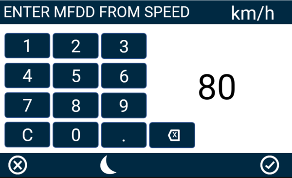
MFDD From Speed Keypad Example
To save the value inputted, press the Confirm button on the bottom right of the screen, or press the Cancel Button on the bottom left of the screen to return to the Settings screen without saving.
Minimum/ Maximum Values
From
- Speed
- The maximum 'From' speed selectable is the value inputted as the Start Speed or Minimum Trigger Speed.
- The minimum 'From' speed selectable is the greater value of 5 km/h or the ‘To’ value +1.
Note: The maximum input value for speed is 999.9 and can be entered up to 1 decimal place.
- Percentage
- The maximum 'From' percentage selectable is 100%
- The minimum 'From' percentage selectable is the ‘To’ value +1.
To
- Speed
- The maximum 'To' speed selectable is the ‘From’ value -1.
- The minimum 'To' speed selectable is the value inputted as the End Speed, or '0' if using a brake trigger.
- Percentage
- The maximum 'To' percentage selectable is the ‘From’ value -1.
- The minimum 'To' percentage selectable is the value inputted as the End Speed expressed as a percentage of configured Start Speed, or '0' if using a brake trigger.
Save Settings
To save the settings to an inserted SD card, select the 'Save Settings' button and enter a suitable file name using the presented keyboard. To save the name, press the Confirm Button on the bottom right of the screen, or press the Cancel Button on the bottom left of the screen to return the Settings screen without saving.
Note: The button will be greyed out if an SD card is not detected.
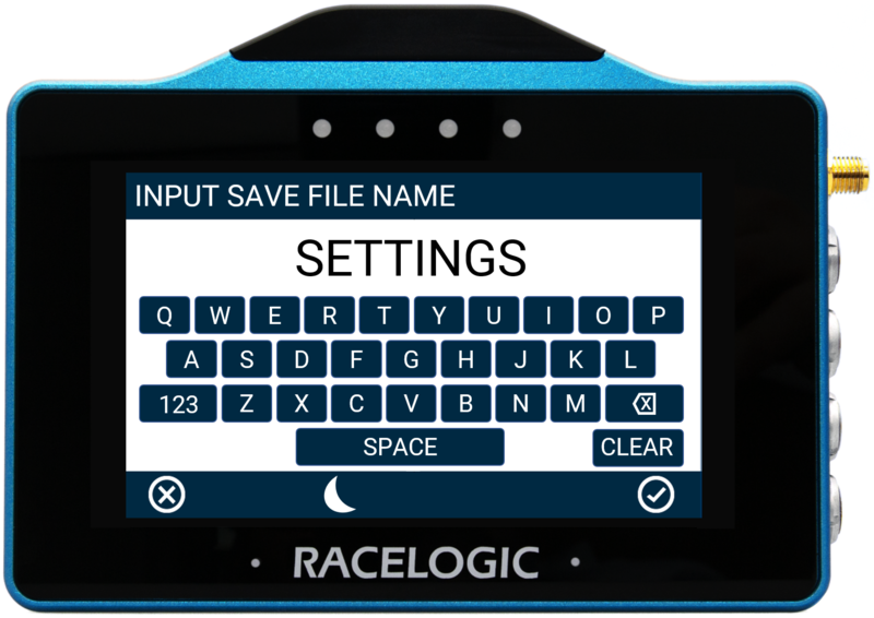
Save Settings Keypad Example
If confirmed, the screen will present a file saved notification, the LEDs will flash green and the unit will emit an audible confirmation notification. If a settings file with the same name already exists on the SD card, the unit will advise that the file is being overwritten, a cancel timeout screen will display, allowing you to cancel the overwriting process within 5 seconds by pressing the screen. If cancelled, the LEDs will briefly flash red and the unit will emit an audible tone, notifying you that the overwriting has been cancelled.
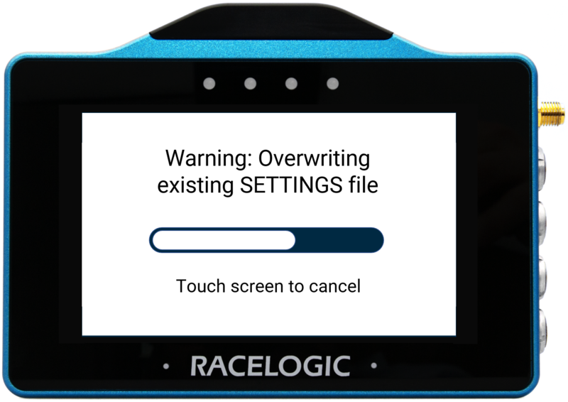 Overwriting screen |
 Save confirmed screen |
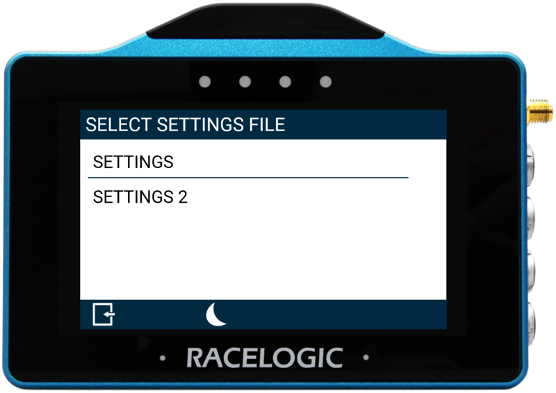
Load Settings
To load a previously saved settings file from an inserted SD card, press the Load Settings button. The unit will present all the available settings files that are located on the SD card. Tap on the desired file and then press the Confirm button at the bottom right of the screen to load it. Press the Cancel button at the bottom left of the screen to return the Settings screen without saving. If you press confirmed, the screen will present a 'file loaded' notification, the LEDs will flash green and the unit will emit an audible confirmation notification.
Note: The button will be greyed out if the unit cannot detect an SD card.