CAN Bus Feature – VBOX Touch 1.5 BETA
CAN Bus
 |
|
The CAN Bus menu is where you can configure the settings for your CAN data capture. The menu is split into two sub-menus, one for each isolated CAN port on the VBOX Touch unit. The ports can be either CAN input, Racelogic (RL) modules or CAN output. Set to CAN output, VBOX Touch will be transmitting its own GNSS derived data to a third party CAN logger. IMPORTANT |
CAN Settings
 |
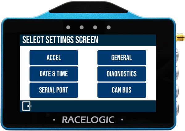
| Your first option is to select which port you want to configure the CAN settings for. Use the Forward and Back arrows in the bottom right-hand corner to navigate between the two ports and their settings. The settings options are the same for both the top and bottom port. |
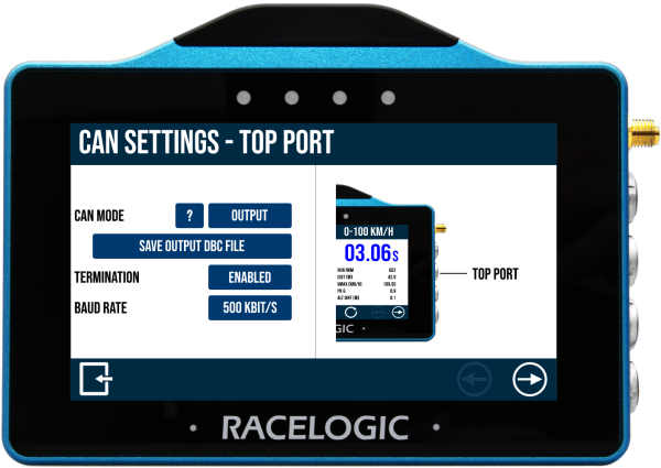
CAN ModeThis setting lets you choose which CAN mode you want to use for this port. You can choose between RL Modules, Input, Output and Disabled. Press on the '?' to see an overview and an explanation of the different CAN modes available. When you have selected the CAN mode you want to use, you will get the option to configure the selected mode. Press the Configure button that appears below your CAN Mode selection. |
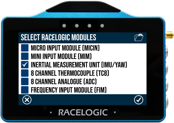
RL ModulesWhen you select to configure the input from a Racelogic Module, you will first have to select the RL modules you are connecting to. You have 6 available modules, and you can choose one or more to connect to. You select them by pressing the respective tick boxes on the left-hand side and pressing the Confirm button to confirm your selection. Press the Cancel button if you want to return to the CAN Mode screen without saving. When you are using RL modules, you have to set them up in VBOX Setup before you can start logging. See example below. Note: You can only use a single like module. If you want to capture data from multiple like modules, you must separate the capture across the two ports, (if both ports are set to capture input from RL Modules, they will only work when two of the same module are connected to the ports), or use Input mode for the capture. To use Input mode to capture multiple like modules, you need to have the modules set to Timed mode, but change the default output identifiers for each additional multiple unit (to something unique) and construct your own (singular) database file that has channels for all the modules you are connecting to. Note:
|
|
Example: How to Set up Racelogic Modules – TC8 and IMU04. |
|
|
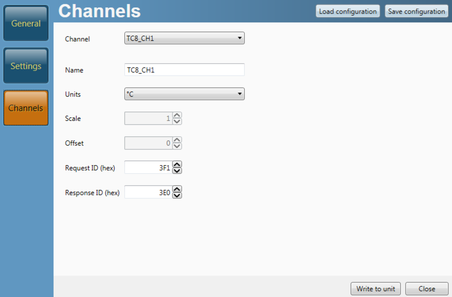
TC8 Connect the TC8 to your PC. The TC8 must be powered by the connection to a powered VBOX unit. Run the VBOX Setup software and select the correct COM port to connect to the TC8. Go to the Settings tab and set the CAN mode to Timed. Check that the other options are configured correctly for your specific setup. Go to the Channels tab and check that the Response ID numbers for each channel are unique. It is important that they do not conflict with the response IDs used by any other connected module (in this case, the IMU04). In this example, the Channel 1 response ID is set to 0x3E0.
|
|
|
IMU04 Connect the IMU04 unit to your PC. The IMU04 must be powered by the connection to a powered VBOX unit. Run VBOX Setup software and select the correct COM port to connect to the IMU04. Go to the Settings tab and set the CAN mode to Timed. Check that the other options are configured correctly for your specific setup. Next, you check the Response ID given to each set channel, to make sure that they are unique and not in conflict with those used by any other module (in this case, the TC8). In this example, we can see that the PitchRate & RollRate response ID is set to 0x602. |
.png?revision=1) |
|
Input Modules When you have confirmed the modules you want to use, you will see the Input Modules screen. This screen is split into halves, with your selected modules on the left-hand side and the logged channels on the right-hand side. Tap on one of the channels on the right-hand side to edit it. |
|
|
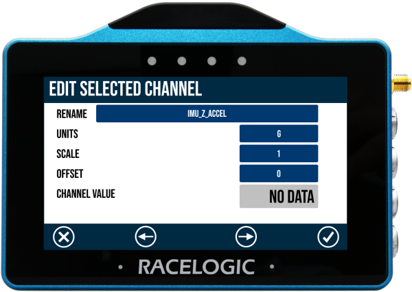
Edit Selected Channel This settings screen has relevant information for the selected channel. You can configure the name, units, scale, and offset, and you can see the channel value if it is connected and transmitting data. Use the forward and back buttons to navigate to the previous or next available channel. Press the Confirm button to confirm your edits and go back to Input modules.
Depending on the selected module, you may get the option to calculate the scale and offset. When you select one of the following modules, you will see a CALC button next to the scale and offset values.
Press the CALC button to open the Scale and offset calculator.
|
 |
InputWhen you select to configure the port to capture CAN Input, you will first have to select which database you are using to decode incoming data. You will get a list of options and can either choose the internal vehicle CAN database or load external DBC files from the SD card to the unit and select from them. To use the internal vehicle database, choose Select from the vehicle CAN database. This will give you a list of available channels for a comprehensive list of makes and models. Select the channels you wish to log by pressing the respective tick boxes on the left-hand side and pressing the Confirm button to confirm your selection. Press the Exit button if you want to return to the CAN Mode screen without saving. Note:
|
.png?revision=1) |
|
Input Modules When you have confirmed the modules you want to use, you will see the Input Modules screen. This screen is split into halves, with your selected modules on the left-hand side and the logged channels on the right-hand side. Tap on one of the channels on the right-hand side to edit it. |
|
|
Edit Selected Channel This settings screen has relevant information for the selected channel. You can configure the name, units, scale, and offset, and you can see the channel value if it is connected and transmitting data. Use the forward and back buttons to navigate to the previous or next available channel. Press the Confirm button to confirm your edits and go back to Input modules.
Depending on the selected module, you may get the option to calculate the scale and offset. When you select one of the following modules, you will see a CALC button next to the scale and offset values.
Press the CALC button to open the Scale and offset calculator.
|
|
|
After you have configured your channels, you will see that the Configure button in the CAN settings has changed to Edit. Press Edit to see the channels you have configured to log. If you want to make a change to the configured channels, press the Change Selection button at the bottom of the screen. You can now add or remove the channels in the currently selected database, or you can press Change Database to choose a different database to select channels from. |
|
OutputBoth ports have the ability to output GNSS and Lap Timing CAN data from the VBOX Touch. You can export and save the CAN database (to decode) directly from the unit to the SD card, Save Output DBC file function. This option will be available when you select Output as your CAN mode. |
|
Termination and Baud RateIn addition to selecting the CAN mode and the logging channels, you can also Disable/Enable Termination and set the Baud Rate. Note: Termination and baud rate are set automatically when you are using the Internal CAN database is used. |
|
.png?revision=1)
.png?revision=1)