02 Hardware Overview - VBOX Video HD2 (v6)

For a quick step-by-step guide to setting up the VBOX Video HD2 system in a vehicle, click here to see the Quick Start Guide.
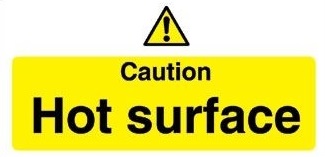
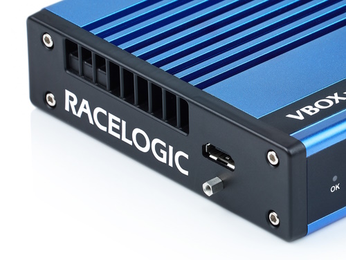
The VBOX Video HD2 is designed to disperse heat from internal components through the lid of the box, as such the unit will become hot to the touch when running.
The enclosure is designed to use airflow to cool the unit down, so do ensure that the top of the HD2 is left open to the air.
If VBOX Video HD2 is being used in extreme ambient temperatures (cabin temperature exceeding 50°C), the Harsh Environment Fan Accessory can reduce the temperature of the unit.
|
IMPORTANT If the HD2 is being used in conjunction with a driver communication radio system, ensure that there is a minimum separation distance of 20 cm between the radio system and the camera units and cables to avoid any video interference problems. |
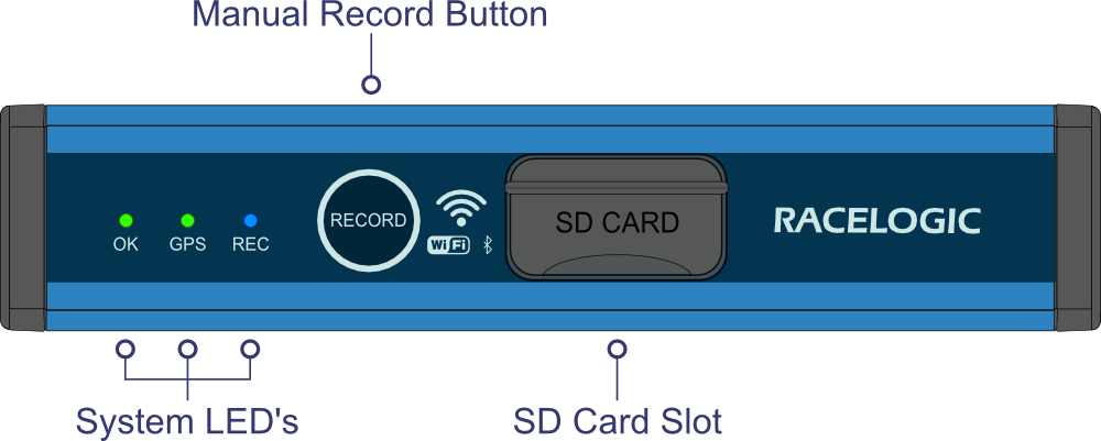
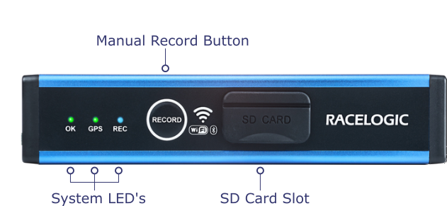
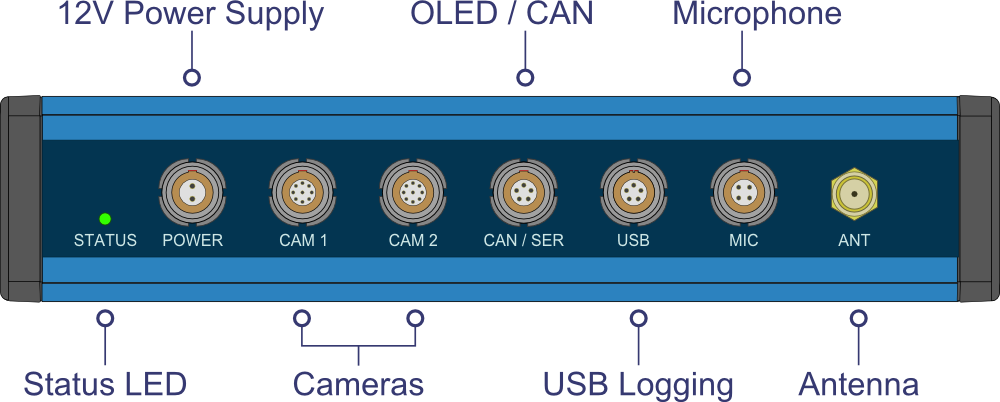
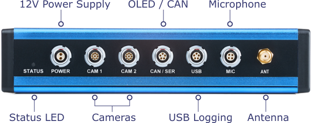
Front Panel
 |
 |
Rear Panel
 |
 |
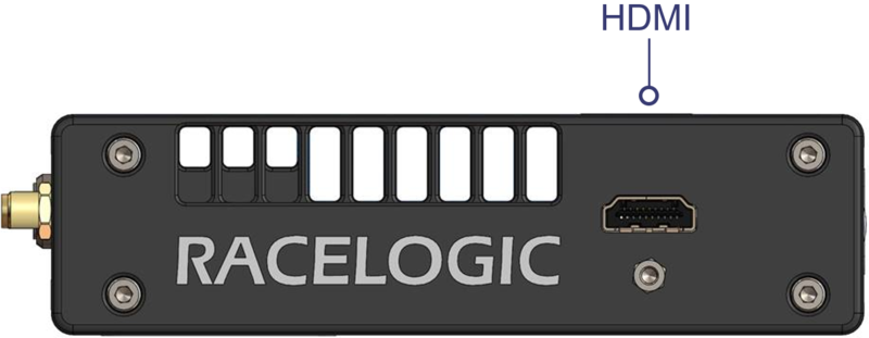
Side Panel
 |
 |
Inputs/ Outputs
Inputs
- 2 x Camera Inputs (CAM 1/CAM 2)
Resolution: 1920 x 1080p or 1280 x 720p at 30 or 60 frames/second (see the Camera specs for your camera to see the relevant specifications)
FOV: 148° horizontal, 86° vertical, 163° diagonal - 2 x Audio Inputs (MIC)
Stereo audio recording with automatic gain control and line level input option - Bluetooth
For start/stop logging switch, heart rate monitor or OBD dongle - RS232 (CAN/SER)
For communication with OLED Display - CAN Bus (CAN/SER)
Allows user to log up to 80 CAN signals
Outputs
- SD Card
Fast 32 GB card supplied with device Fast SD card required – tested up to 512 GB supported - USB 2.0 Host Interface (USB)
For recording to USB flash drives, fast USB drive required - WiFi
For camera setup/preview - RS232 (CAN/SER)
For communication with OLED Display - HDMI video output (side connector)
HDMI 1.3 with EIA/CEA-861-D video format support
Maximum pixel rate of 74.25 MHz at 1080p30
LED Behaviour
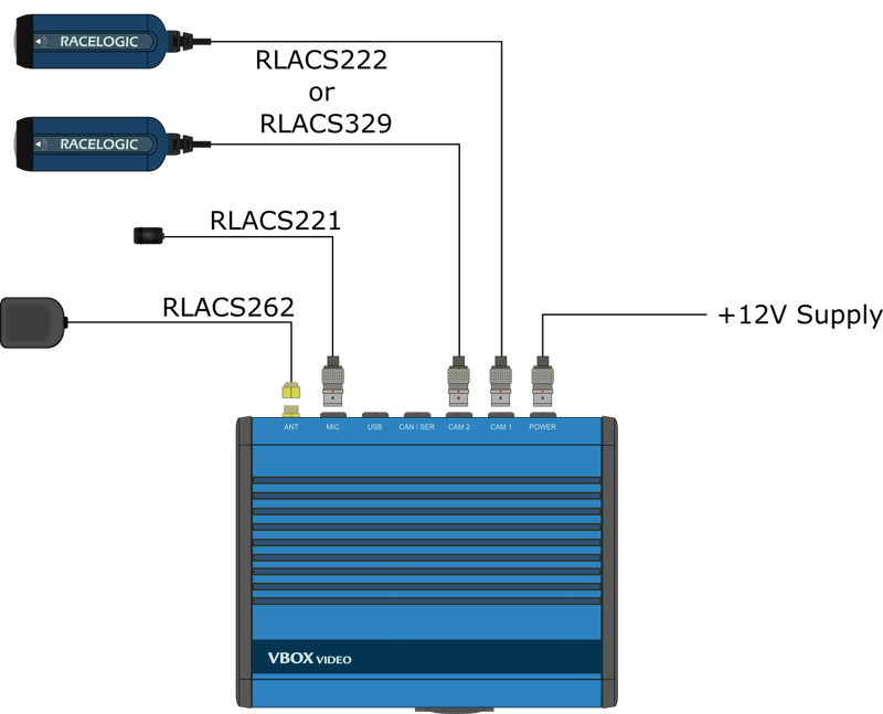
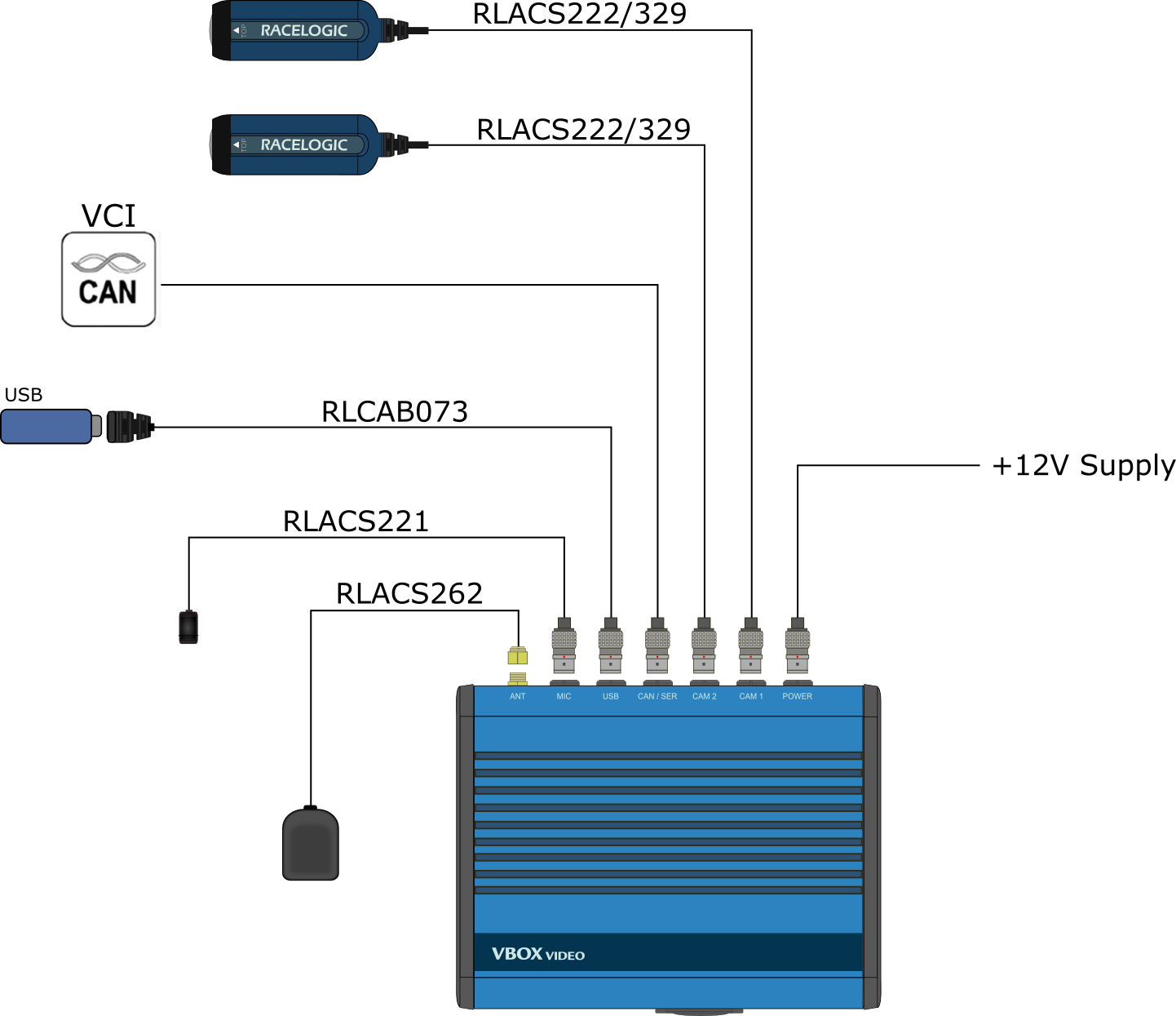
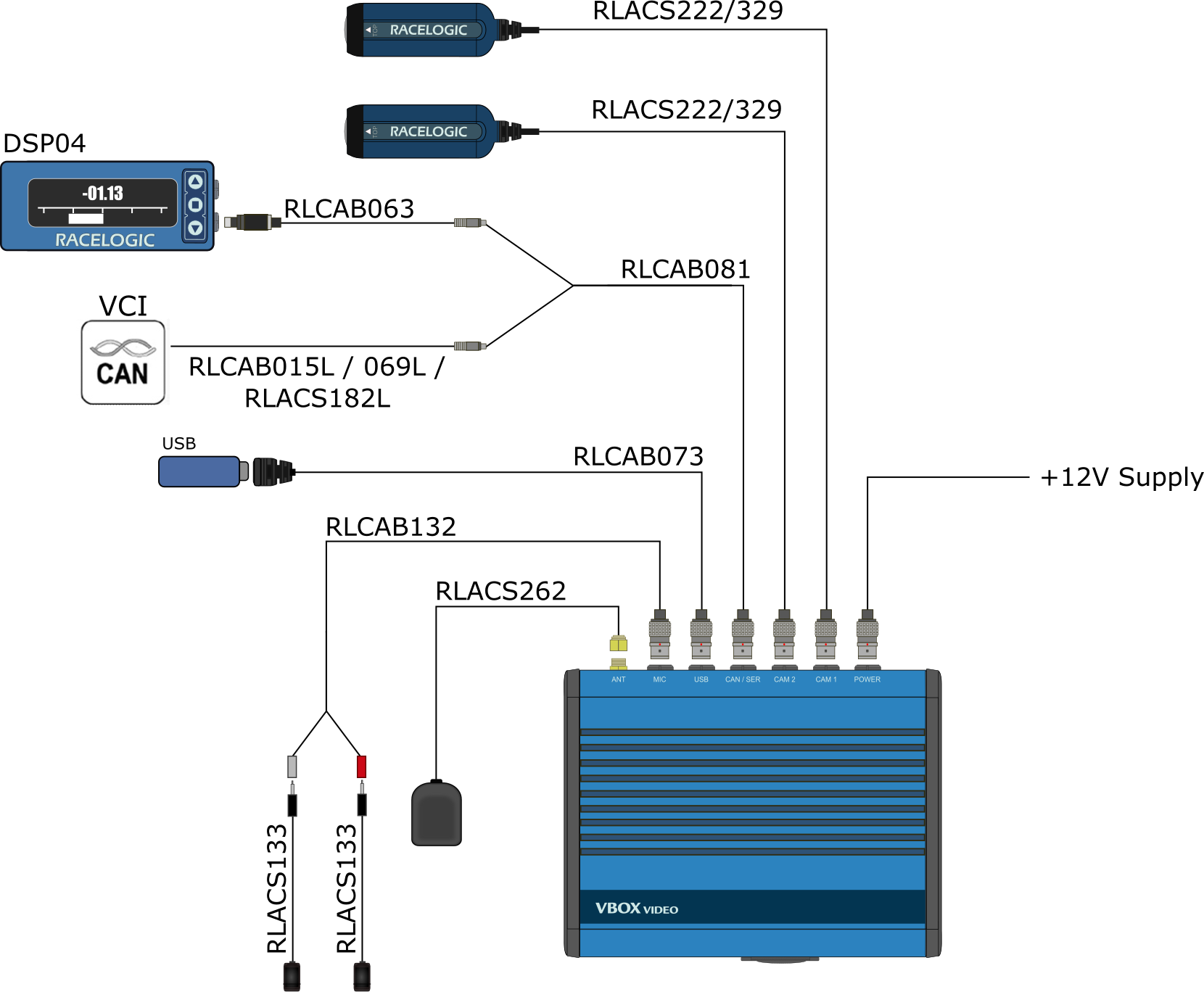
Connection Diagrams
Information on connecting different types of OLED display is available here.
Supplied equipment
Including OLED Display and USB Logging
Including CAN and Stereo Microphones
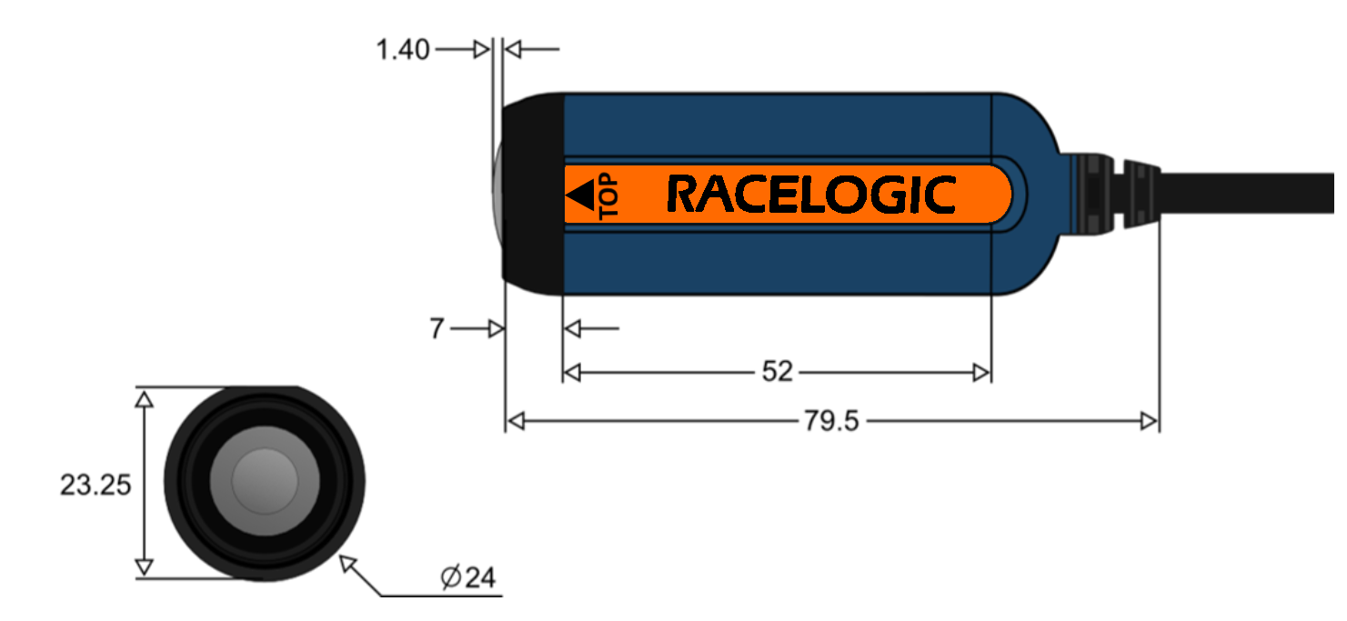
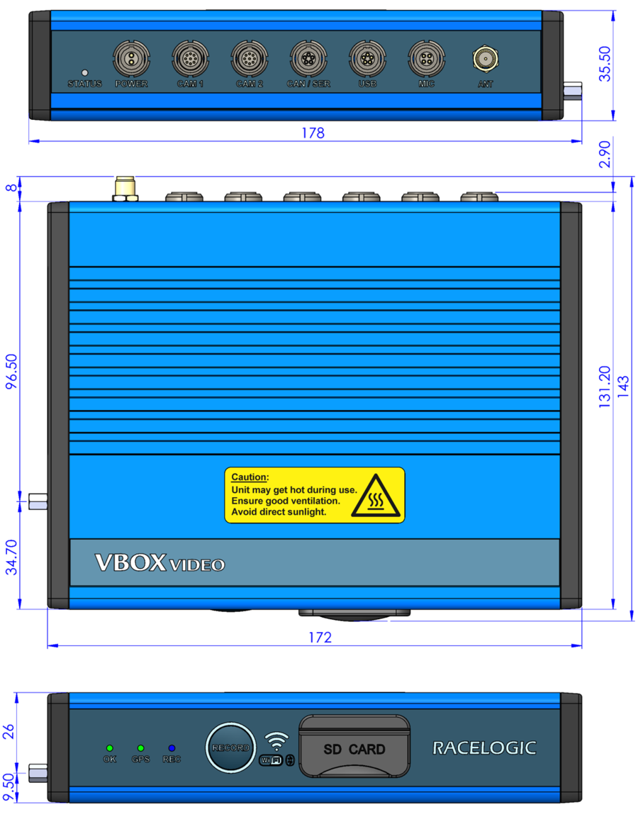
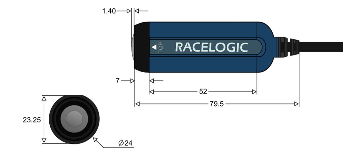
Unit Dimensions
Measurements all displayed in mm.
RLACS222
RLACS329