When loading a file into Circuit Tools 3, it will automatically detect the country, circuit and track configuration from our integrated Track Map Database. The data in the file is synchronised with the lap videos in the Video Pane and a cursor representing the vehicle moving along the track in the Track Map Pane.
You can view the full user guide for Circuit Tools 3 here.
Downloading the Software
Download Circuit Tools 3 from the VBOX Motorsport website.
Double-click on the installer to install the software on your device.
When you run the software for the first time, it will open with a blank screen.
Load a file to view the data and get access to the full functionality.
Load Files
Before you load a file, you should copy the .VBO files and any linked video files from the data logger's SD card to a folder on your computer. This is essential if you are using video for your analysis, as it will speed up the software. The easiest way to transfer files from the SD card is to use Circuit Tools 3, which has an inbuilt file transfer functionality.
NOTE
If your video files are large, consider using the fastest SD card you can purchase, with a USB 3.0 reader (make sure your laptop has USB 3.0).
VBOX Files
Method 1: Using the Mouse
- Click File.
- Click the Load VBO File button to open the Open VBOX File dialogue.
Method 2: Using the Keyboard Shortcut
- Press [F3] to open the Open VBOX File dialogue.

Method 1: Using the Mouse
- Click File.
- Click the Load VBO File button to open the Open VBOX File dialogue.
Method 2: Using the Keyboard Shortcut
- Press [F3] to open the Open VBOX File dialogue.

The Open VBOX File dialogue will display the following file information:
- Name
- Circuit
- Number of Laps
- Best Lap
- Session Length
- Date modified
- File Size
- A video preview

This allows you to quickly select the relevant files for your analysis.
In addition to the Video Preview, the right-hand pane in the dialogue will also contain the following:
- The option to Edit Session Data
- Transfer Wizard (only present if an SD card is detected)
When the files are opened, Circuit Tools 3 will use the GPS position in the file to automatically detect the circuit and load it from our Track Map Database. If there are multiple track layouts, Circuit Tools 3 will use the length of a lap to select the correct layout. You can change the track layout manually later.
NOTE
Circuit Tools 3 cannot open files from more than one track location at the same time.
Sector Files
If the circuit or location in your file is not supported by our Track Map Database, you can load a sector/split file to apply user-defined sectors to the Track Map and Graph.
- Click File
- Click the Load Sectors button to open File Explorer
- Navigate to the required file and click Open

- Click File
- Click the Load Sectors button to open File Explorer
- Navigate to the required file and click Open

NOTE
To apply the sectors from the loaded sector/split file in Circuit Tools 3, you must select the sector method User defined in the Track Map Options.
Transfer Files
Run the software and click File → Load VBO File to open the Open VBOX file dialogue. The dialogue will automatically detect and analyse inserted SD cards and determine the track in the file, create and name the folder using the circuit name, and create a subdirectory for the numbered session.
At this point, you can rename the session to something suitable (such as "Qualifying"). Click Move to copy the files across from the SD card to the new folder and delete the files on the SD card, or Copy to create a copy of the files in the new folder and leave the original files on the SD card.

Set Start/Finish Line(s)
If the circuit in the file does not exist in the Track Map Database, you must set the Start/Finish line(s) for the track.
To define the Start/Finish line, click on the required location on the Track Map.
Use one of the two following methods:
- Right-click on the map and click Set Start/Finish line or Set Separate Finish.
- Click on the Track Map Options button on the Toolbar and click Set Start/Finish line or Set Separate Finish.
Screen Layout
Toolbar

The toolbar in Circuit Tools 3 has been simplified to give you quick access to the most frequently used controls and options.
- Click on File to open the dropdown menu and access options for loading files into the software, exporting files, information about the software, and recently loaded files. You can also exit the software from here.
- Click on Clear to remove all loaded sessions from Circuit Tools 3.
- Click View to open the dropdown menu where you can adjust the screen layout.
- Click Laps/Sessions to change the focus between separate laps and the overall session(s).
- Click Channels to open the dropdown list of available CAN channels in the file to select the channels you want to analyse in the Graph pane.
- Click Maths to open the Channel Setup - Maths Channel dialogue and select or create maths channels for your analysis.
- Click Reports to open the Reports window and compare different data of different laps in a user-friendly histogram interface.
- Use the Video Controls on the toolbar to control the video playback.
- Click Track to open the dropdown lists of available track layouts for the track location in the file.
- Click Track Options to open the dropdown menu with options for the map, such as lines, sectors, pit lanes, etc.
- Click Settings to open the Settings window where you can access settings for General, Laps and Sectors, Graph, Video, and Track Map.
- Click Help to open the Circuit Tools 3 - Quick Start Guide on the Support Centre.
Progress Bar

The Progress Bar will be displayed on the Toolbar when Circuit Tools 3 is performing an operation that may take some time. It will provide feedback on the remaining time for the currently ongoing operation.
Maths Channels
Click the Maths button to open the Maths Channels Setup window.
You can either select pre-configured maths channels from the Standard Maths Library or create your own maths channels.

Standard Maths Library
Select a maths channel from the library to view details about it in the pane on the right-hand side. These details will contain the name and description, any relevant options that need to be configured for your file, and the option to add the maths channel to the graph.

Create New
Click the Add button to open the configuration pane for new maths channels.
The channel will automatically be named "MathsX", where X is the next consecutive number after the highest existing number.
You can change the name in the configuration pane.
The configuration pane contains a description field, an expression field, a unit field and the option to add the maths channel to the graph.

Reports
Click on the Reports button to open the Reports Dialogue.
Click on the histogram to display/hide the labels on the graph.

Channel
Click on the Channel dropdown to open the dropdown list and select the channel you want to view in the histogram.
Orientation
Select the orientation for the histogram:
- Vertical
- Horizontal
Lap(s)
Click on the Lap(s) dropdown to open the dropdown list and select the laps you want to compare in the histogram.
Sector(s)
Click on the Sector(s) dropdown to open the dropdown list and select the relevant sector(s) (if available).
Number of Ranges
Circuit Tools 3 will automatically apply the most suitable number of ranges, but you can enter the required number of ranges in this field to apply them instead.
Start From
Circuit Tools 3 will automatically apply the most suitable number to start from, but you can enter the required start number in the field to apply it instead.
Interval
Circuit Tools 3 will automatically apply the most suitable interval number, but you can enter the required interval in the field to apply it instead.
Use absolute channel values
Tick the Use absolute channel values box to apply absolute values to the histogram.
Laps Pane
The Laps Pane contains a table view with all the laps from a loaded file. If you load multiple files (sessions), you will see one tab for each file/session at the top of the pane.
These laps have been defined using the Start/Finish line for the track in the file. If you have loaded a file with a track that is not in the Track Map Database, you must set the Start/Finish line(s) for the track manually. You can do this in the Track Map Pane.
When viewing laps, you can select up to 6 laps to compare by ticking their boxes in the Show column.
The text for any lap sectors slower than the reference lap will be red, the text for any lap sectors quicker than the reference lap will be green, and the fastest lap sector across all laps will be purple.
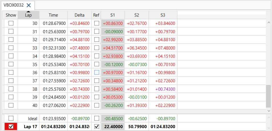
Laps Table
The Laps pane has a table with the following columns:
- Show: Contains a tick box for each lap. Tick a box to select a lap and have Circuit Tools 3 display it in the Graph, Map and Video panes.
- Lap: Contains the number of the lap in order of creation.
- Time: Contains the total time for each lap.
- Delta: Contains the delta time for each lap compared to the reference lap.
- Ref: Contains a tick box for each lap. Circuit Tools 3 will automatically select the fastest lap as the reference lap. You can change this by ticking the box for the lap you want to use instead. You can only tick one box at a time.
- S1-SX: Contains the delta time spent in each sector of the track. The text in the cell will be coloured based on a comparison with the reference lap.
- Bottom Rows
At the bottom of the table, there will be some default fixed rows.
The Ideal Lap (when generated) will be created and displayed at the bottom of the laps table.
The Reference Lap will be copied and displayed at the bottom of the laps table for easy comparison.
The Multi Lap will be created and displayed if you load more than one file/session at the same time.
Ideal Lap
The Ideal lap displays a lap time based on the fastest sector times across all the laps in the session to provide the best possible lap based on the logged data.
When you tick this box, Circuit Tools 3 will create a synchronised video and add it to the Video Pane so that you can view it alongside any other selected laps. You can also set the Ideal Lap as the reference lap.
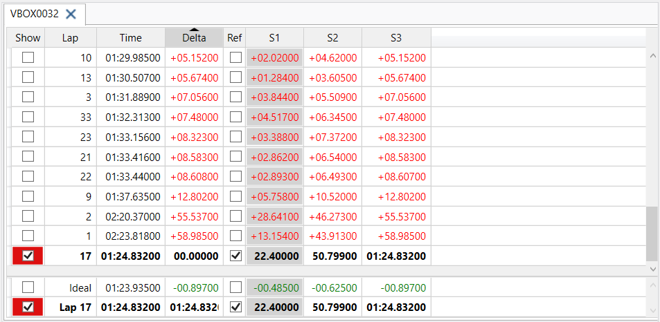
Reference Lap
The Reference Lap is by default the fastest lap in the loaded file/session. You can change this by ticking the Ref box for a different lap. All splits, lap time comparisons, and Delta-T values are relative to the selected reference lap.
Multi Lap
The Multi Lap is the ideal lap across multiple files and will only be generated and displayed when you load two or more files simultaneously. It consists of the fastest sector times across all the laps in all the sessions to provide a theoretically best possible lap based on the logged data. When you tick the Show box to select the Multi Lap, Circuit Tools 3 will create a synchronised video and add it to the Video Pane, so that you can view it alongside any other selected laps. You can also set the Multi Lap as the reference lap.

You can select maps from all loaded files/sessions to compare in the Video, Graph and Track Map panes.
Change Order of Laps
The laps in a session are by default listed in chronological order. You can change the order of the laps by clicking the column header you want to sort it by. Click once to sort in descending order and again to sort in ascending order.
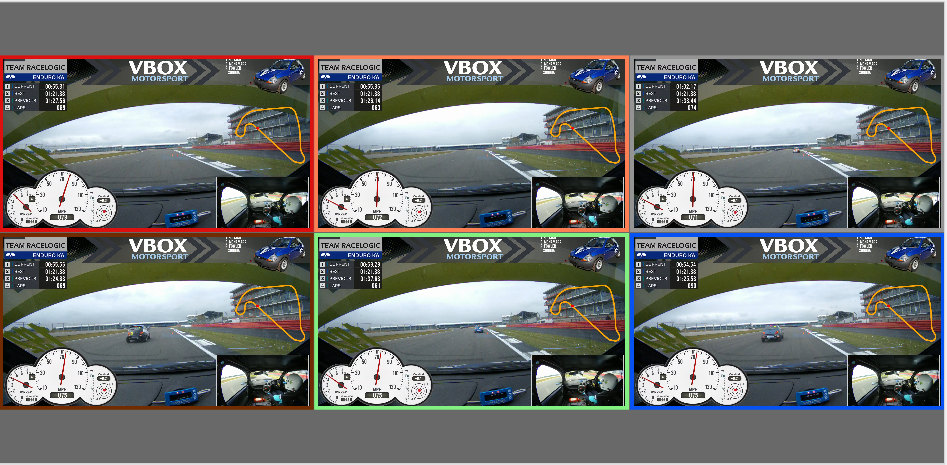
Video Pane
The Video Pane will display the video(s) associated with the selected lap(s) in the Laps Pane. You can select up to 6 laps to view/compare.
Playback Controls

- Start the playback of the video(s)

- Start the playback of the video(s)

- Pause the video(s)
Changes from Play symbol.

- Pause the video(s)
Changes from Play symbol.

- 1st click will stop the video playback.
- 2nd click will jump to the last stop position.
- 3rd click will jump to the beginning of the section displayed in the graph.

- 1st click will stop the video playback.
- 2nd click will jump to the last stop position.
- 3rd click will jump to the beginning of the section displayed in the graph.

- Jump back to the last stop position
Changes from Stop symbol

- Jump back to the last stop position
Changes from Stop symbol

- Jump back to the start of the section shown in the Graph window
Changes from Jump Back symbol

- Jump back to the start of the section shown in the Graph window
Changes from Jump Back symbol

Playback Speed: Adjust the playback speed between x0.25 and x4.

Playback Speed: Adjust the playback speed between x0.25 and x4.

Toggle playback
Method 1: Using the Mouse
Toggle the video playback on or off by clicking on the Video Pane or by clicking on the Playback Controls in the Toolbar.
Method 2: Using the Keyboard Shortcuts
Toggle the video playback on or off by pressing Spacebar, Enter or P.
Jump back to the last stopped position
Method 1: Using the Mouse
Jump to the last stop position by clicking on the Playback Controls in the Toolbar.
Method 2: Using the Keyboard Shortcuts
Jump to the last stop position by pressing Backspace or Num 0.
Press the key a second time to return the marker to the start of the section that is displayed in the Graph pane.
Change the playback speed
Method 1: Using the Mouse
Change the playback speed by clicking on the Playback Speed dropdown in the Toolbar and selecting the required speed.
Method 2: Using the Keyboard Shortcuts
Change the playback speed with the + and - keys on the main keyboard (not the numeric keypad).
You can see the full list of keyboard shortcuts here.
Auto-Generate Ideal Laps
You can enable/disable the automatic generation of Ideal Laps in Toolbar → Settings → Video.
- When this is disabled and you create a new Ideal Lap or Multi Lap for the first time for that session or change the sectors, start/finish line or loaded files in any way, Circuit Tools 3 will add a placeholder video frame to the Video Pane. but it will not generate the video until you click in the placeholder frame.
- When this is enabled and you create a new Ideal Lap or Multi Lap for the first time for that session or change the sectors, start/finish line or loaded files in any way, Circuit Tools 3 will automatically generate the video and add it to the Video Pane.
Show Lap Name on Video
You can make Circuit Tools 3 display the name of a lap (the lap number) in the video overlay by going to Toolbar → Settings → Video.
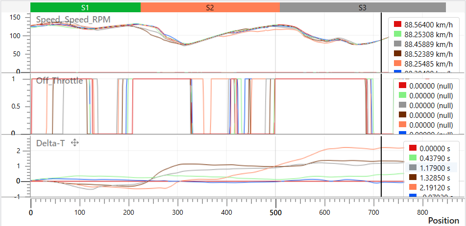
Graph Pane
The graph pane will plot the selected lap(s) against the selected channel(s), including the track sectors. The X-axis is, by default, the Position on the track. You can change this to Distance or Time in Toolbar → Settings → Graph. The Y-axis can be any channel available in the file. The track sectors are marked on the graph to make it easier to judge the position compared to the Track Map and Laps data.
The channel value at the cursor position will be displayed in the data window. The lap(s) will have the same colour on the trace as they have in the Laps Pane. By default, the fastest lap will be red.
Zooming and Panning
The quickest way to zoom in the Graph pane is by using the scroll function on the mouse or the up and down arrow keys. The scroll function will zoom on the X-axis by default, but you can zoom on the Y-axis by hovering over it and scrolling to zoom in/out. Alternatively, you can use the mouse to left-click on a Graph in the Graph Pane and draw a zoom box from left to right to zoom in and from right to left to zoom out.
You can use the left and right arrow keys to move along the X-axis on the graph, or use the mouse to right-click on the graph and drag to pan the zoomed graph.
Overlaying Channels
You can overlay channels to compare the data traces on a common Y-axis.
You can drag and drop a channel graph onto the graph you want to overlay it with. To do this. you must first hover over the channel name until you see the Drag icon appear, and then left-click and drag the channel graph to the graph you want to overlay it with.
The recipient graph will be framed by a green box to highlight that your channel can be added to it to produce an overlay of the signal traces.
By default, all channels will remain the same colour when you overlay them, but you can change the channel colours by clicking on the respective coloured rectangle in the data window and selecting a new colour.
X-Axis
There are three ways of aligning comparison data: Time, Distance and Position. You can select the method you want to use in Toolbar → Settings → Graph.
Position is the default parameter for the X-axis, and this is the method recommended for comparing two different laps.
Traditionally, rolling distance has been used to align laps, but with the advantage of GPS, it is better to use GPS position to get a more accurate position. As the distance travelled around a lap varies from lap to lap depending on the driving line (often > 30 m), the error margin in GPS is much lower than the variation in rolling distance.
Using GPS position alignment also makes the Delta-T value very accurate. This makes the values meaningful, even on a track like the Nordschleife, where a Delta-T or predictive lap time based on distance would only be accurate to around 1 – 2 seconds after a full lap.
IMPORTANT
Graphing using the Position method relies on good GPS position data.
If you lose GPS position or you have heavy tree cover, it is best to switch back to Distance or even Time.
If you leave the track or cut out a part of the circuit, you will also get a poor position-based comparison and may even be unable to play the video or move the graph cursor beyond the point where you left the circuit.
Smoothing
You can change the level of smoothing applied to the acceleration channels displayed in the Graph, such as lateral and longitudinal acceleration. Applying higher levels of smoothing will produce a cleaner-looking graph; however, it will also reduce the accuracy of the displayed results.
You can select the smoothing type and level in Toolbar → Settings → Graph and locate the Acceleration Smoothing option.
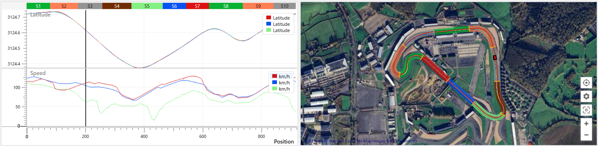
Track Map Pane
Circuit Tools 3 has a Track Map Pane that will display a satellite map of the track detected in the loaded file.
The start/finish line will be indicated by a checkered line.
The different sectors will be displayed by default and are separated by yellow lines. You can remove the sector display, enable sector highlighting or change the colour scheme of the sector highlighting in the Map Settings.
Selected laps will be added to the map with traces in colours that correspond to the colours in the Laps Pane. Each lap will also have a cursor on the track that will be synchronised with the video and the graph. You can change the cursor type in Toolbar → Settings → Track Map.
You can move the cursor to a specific location on the track by clicking on the track in the Track Map Pane.
You can pan the map by hovering over the map and clicking and holding both mouse buttons at the same time and dragging the map around.

Map Settings

Centre on Vehicle
Click on this button to centre the map on the vehicle (cursor). The map will follow the vehicle when you start the playback.

Click on this button to centre the map on the vehicle (cursor). The map will follow the vehicle when you start the playback.

Click on this button to stop centring the map on the vehicle (cursor).

Click on this button to stop centring the map on the vehicle (cursor).

Settings
Click on this button to open the menu and access the following settings:

Click on this button to open the menu and access the following settings:

Sector Highlighting

Tick the Sector Highlighting tick box to enable/disable sector highlighting on the map.
When it is enabled, you can click on the Sector Highlighting colour dropdown arrow to open the list and choose the required scheme. You will have the following options:
- Two Colour Light
- Two Colour Dark
- Multi-Coloured
- High Contrast
Map Provider

You can change the map provider for the Track Map. Click on the Map Provider dropdown arrow to open the list and select the required provider. You will have the following options:
- None
- Bing
Reset Zoom
If you have applied zoom to the Track Map, you can click this button to reset the zoom to the default level.

If you have applied zoom to the Track Map, you can click this button to reset the zoom to the default level.

Zoom in/out
Click on the + and - buttons to zoom in or out on the Track Map.

Click on the + and - buttons to zoom in or out on the Track Map.

Right-click on the map to access the on-map version of the Track Map Options:

Sectors
Circuit Tools 3 will automatically divide the laps into sectors by using the points on the track that correspond to maximum speed.
You can change how Circuit Tools 3 splits the lap into sectors. To do this, you have to open the Track Map Options, where you will have the following options:
- Equal distance: Split the lap(s) into X number of sectors of equal distance.
- Max speed: Divide the lap(s) into sectors based on the points on the track that correspond to maximum speed.
- Max accel/decel: Divide the lap(s) into sectors based on the points on the track that correspond to maximum acceleration and deceleration.
- User defined: Load an .SPL file into Circuit Tools 3 with pre-set splits for the lap sectors. You can do this via Toolbar → File → Load Sectors.
NOTE
When Equal Distance is selected, you can set the number of sectors you want the lap split into in Toolbar → Settings → Lap and Sectors.
Sector Highlighting
You can toggle the sector highlighting in the Track Map Pane on and off. You can either right-click in the Track Map Pane and select Toggle Sector Highlighting, or you can open the Track Map Options and select/deselect the Sector Highlighting option there.
The sector highlighting will be Multi-Coloured by default, but you can go to Toolbar → Settings → Laps and Sectors or use the Settings button directly on the Track Map to change it.
Settings
In addition to the options for sector display and highlighting, you can find the following options in Toolbar → Settings → Laps and Sectors:
- Sector Time format
- Equal Sectors per Lap
- Gate width