View Layout
With No File Loaded
When you first open the software, the user interface will be displayed with no data. The available panes in the user interface will be displayed by default.
- Laps
- Video
- Graph
- Track Map
You can select the panes you want displayed in the View dropdown on the Toolbar.
To gain access to all the features in Circuit Tools 3, you must first load a file.
Loading a File
When you load a file in Circuit Tools 3, the data will be displayed in the respective panes of the user interface.
You can now access the full range of features and settings in Circuit Tools 3.
When a file is replaying, the data in the Graph, the Video and the Track Map will be synced. If you select a point in the Graph or on the Track Map, the other panes will automatically jump to the same point in the file.
You can find a list of the available keyboard shortcuts for the different Panes and functionalities here.

Sectors
Circuit Tools 3 will automatically divide the laps into sectors by using the points on the track that correspond to maximum speed.
These not only give a usable number of sectors, but they also make sure that the Ideal lap is realistic, as it takes into account the slowing down and acceleration out of each major corner.
Sector Options
You can change how Circuit Tools 3 splits the lap into sectors. To do this, you have to open the Track Map Options and select between the following options:
- Equal distance
Split the lap(s) into X number of sectors of equal distance. - Max speed
Divide the lap(s) into sectors based on the points on the track that correspond to maximum speed. - Max accel/decel
Divide the lap(s) into sectors based on the points on the track that correspond to maximum acceleration and deceleration. - User defined
Load an .SPL file into Circuit Tools 3 with pre-set lap sectors. You can do this via the Load Sectors option in the File menu.
| Note: When Equal Distance is selected, you can set the number of sectors you want the lap split into in the Lap and Sectors settings. |
Sector Highlighting
You can toggle the sector highlighting in the Track Map Pane on and off. You can either right-click in the Track Map Pane and select Toggle Sector Highlighting, or you can open the Track Map Options and select/deselect the Sector Highlighting option there.
The sector highlighting will be Multi-Coloured by default, but you can go to Toolbar -> Settings -> Laps and Sectors or use the Settings button directly on the Track Map to change it.
You can select between:
Two Colour (Light)

Two Colour (Dark)

Multi-Coloured

High Contrast

Settings
In addition to the options for sector display and highlighting, you can find the following options in Toolbar -> Settings -> Laps and Sectors:
- Sector Time format
- Equal Sectors per Lap
- Gate width
Laps Pane
The Laps Pane contains a table view with all the laps from a loaded file. If you load multiple files (sessions), you will see one tab for each file/session at the top of the pane.

These laps have been defined using the Start/Finish line for the track in the file. If you have loaded a file with a track that is not in the Track Map Database, you must set the Start/Finish line(s) for the track manually. You can do this in the Track Map Pane.
When viewing laps, you can select up to 6 laps to compare by ticking their boxes in the Show column.
The lap times in each sector will be colour-coded:
Laps slower than the reference lap will be red.
Laps quicker than the reference lap will be green.
The fastest lap in the sector will be purple.

|
Notes:
|
Laps Table
The Laps pane has a table with the following columns:
- Show
Contains a tick box for each lap. Tick a box to select a lap and have Circuit Tools 3 display it in the Graph, Map and Video panes. - Lap
Contains the number of the lap in order of creation. - Time
Contains the total time for each lap. - Delta
Contains the delta time for each lap compared to the reference lap. - Ref
Contains a tick box for each lap. Circuit Tools 3 will automatically select the fastest lap as the reference lap. You can change this by ticking the box for the lap you want to use instead. You can only tick one box at a time. - S1-SX
Contains the delta time spent in each sector of the track. The text in the cell will be coloured based on a comparison with the reference lap.
- Bottom Rows
At the bottom of the table, there will be some default fixed rows.
The Ideal Lap (when generated) will be created and displayed at the bottom of the laps table.
The Reference Lap will be copied and displayed at the bottom of the laps table for easy comparison.
The Multi Lap will be created and displayed if you load more than one file/session at the same time.
Ideal Lap
The Ideal lap displays a lap time based on the fastest sector times across all the laps in the session to provide the best possible lap based on the logged data.
When you tick this box, Circuit Tools 3 will create a synchronised video and add it to the Video Pane so that you can view it alongside any other selected laps. You can also set the Ideal Lap as the reference lap.
Reference Lap
The Reference Lap is by default the fastest lap in the loaded file/session. You can change this by ticking the Ref box for a different lap. All sectors, lap time comparisons, and Delta-T values are relative to the selected reference lap.
Multi Lap
The Multi Lap is the ideal lap across multiple files and will only be generated and displayed when you load two or more files simultaneously. It consists of the fastest sector times across all the laps in all the sessions to provide a theoretically best possible lap based on the logged data. When you tick the Show box to select the Multi Lap, Circuit Tools 3 will create a synchronised video and add it to the Video Pane, so that you can view it alongside any other selected laps. You can also set the Multi Lap as the reference lap.

You can select maps from all loaded files/sessions to compare in the Video, Graph and Track Map panes.
Change Order of Laps
The laps in a session are by default listed in chronological order. You can change the order of the laps by clicking the column header you want to sort it by. Click once to sort in descending order and again to sort in ascending order.

Display VMax
You can view the VMax for each lap by enabling the Display VMax Column in the Laps and Sectors settings.
Video Pane
The Video Pane will display the video(s) associated with the selected lap(s) in the Laps Pane. You can select up to 6 laps to view/compare. Watch the videos side by side in slow motion to see the lines taken by each driver.

|
Note: If you are viewing the data in laps, the Video pane will add a video frame for each selected lap. If you are viewing the data in sessions, the Video pane will add a video frame for each loaded session (file). |
Toggle playback
Method 1: Using the Mouse
Toggle the video playback on or off by clicking on the Video Pane or by clicking on the Playback Controls in the Toolbar.
Method 2: Using the Keyboard Shortcuts
Toggle the video playback on or off by pressing Spacebar or Enter.
Jump back to the last stopped position
Method 1: Using the Mouse
Jump to the last stop position by clicking on the Playback Controls in the Toolbar.
Method 2: Using the Keyboard Shortcuts
Jump to the last stop position by pressing Backspace or Num 0.
Press the key a second time to return the marker to the start of the section that is displayed in the Graph pane.
Change the playback speed
Method 1: Using the Mouse
Change the playback speed by clicking on the Playback Speed dropdown in the Toolbar and selecting the required speed.
Method 2: Using the Keyboard Shortcuts
Change the playback speed with the + and - keys on the main keyboard (not the numeric keypad).
You can see the full list of keyboard shortcuts here.
Ideal Lap Video
You can enable/disable the automatic generation of Ideal Laps in Toolbar -> Settings -> Video.
- When this is disabled and you create a new Ideal Lap or Multi Lap for the first time for that session or change the sectors, start/finish line or loaded files in any way, Circuit Tools 3 will add a placeholder video frame to the Video Pane. but it will not generate the video until you click in the placeholder frame.
- When this is enabled and you create a new Ideal Lap or Multi Lap for the first time for that session or change the sectors, start/finish line or loaded files in any way, Circuit Tools 3 will automatically generate the video and add it to the Video Pane.
Graph Pane
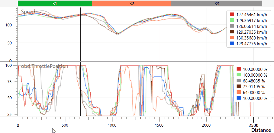
The graph pane will plot the selected lap(s) against the selected channel(s), including the track sectors. The X-axis is, by default, the Position on the track. You can change this to Distance or Time in Toolbar -> Settings -> Graph. The Y-axis can be any channel available in the file. Speed and Delta-T will be selected by default when you open Load a file for the very first time. The track sectors are marked on the graph to make it easier to judge the position compared to the Track Map and Laps data.
The channel value at the cursor position will be displayed in the data window. The lap(s) will have the same colour on the trace as they have in the Laps Pane. By default, the fastest lap will be red. You can change the colour of the lap trace in the Graph by clicking on the respective coloured rectangle in the data window and selecting a new colour.

Zooming and Panning
The quickest way to zoom in the Graph pane is by using the scroll function on the mouse or the up and down arrow keys. The scroll function will zoom on the X-axis by default, but you can zoom on the Y-axis by hovering over it and scrolling to zoom in/out. Alternatively, you can use the mouse to left-click on a Graph in the Graph Pane and draw a zoom box from left to right to zoom in and from right to left to zoom out.
You can use the left and right arrow keys to move along the X-axis on the graph, or use the mouse to right-click on the graph and drag to pan the zoomed graph.
Overlaying Channels
You can overlay channels to compare the data traces on a common Y-axis.
You can drag and drop a channel graph onto the graph you want to overlay it with. To do this. you must first hover over the channel name until you see the Drag icon appear, and then left-click and drag the channel graph to the graph you want to overlay it with.
The recipient graph will be framed by a green box to highlight that your channel can be added to it to produce an overlay of the signal traces.
By default, all channels will remain the same colour when you overlay them, but you can change the channel colours by clicking on the respective coloured rectangle in the data window and selecting a new colour.
X-Axis
There are three ways of aligning comparison data: Time, Distance and Position. You can select the method you want to use in Toolbar -> Settings -> Graph.
Position is the default parameter for the X-axis, and this is the method recommended for comparing two different laps.
Traditionally, rolling distance has been used to align laps, but with the advantage of GPS, it is better to use GPS position to get a more accurate position. As the distance travelled around a lap varies from lap to lap depending on the driving line (often > 30 m), the error margin in GPS is much lower than the variation in rolling distance.
Using GPS position alignment also makes the Delta-T value very accurate. This makes the values meaningful, even on a track like the Nordschleife, where a Delta-T or predictive lap time based on distance would only be accurate to around 1 – 2 seconds after a full lap.
|
IMPORTANT Graphing using the Position method relies on good GPS position data. If you lose GPS position or you have heavy tree cover, it is best to switch back to Distance or even Time. If you leave the track or cut out a part of the circuit, you will also get a poor position-based comparison and may even be unable to play the video or move the graph cursor beyond the point where you left the circuit. |
Smoothing
You can change the level of smoothing applied to the acceleration channels displayed in the Graph, such as lateral and longitudinal acceleration. Applying higher levels of smoothing will produce a cleaner-looking graph; however, it will also reduce the accuracy of the displayed results.
You can select the smoothing type and level in Toolbar -> Settings -> Graph and locate the Acceleration Smoothing option.
Track Map Pane
Circuit Tools 3 has a Track Map Pane that will display a satellite map of the track detected in the loaded file.

The start/finish line will be indicated by a checkered line.
The different sectors will be displayed by default and are separated by yellow lines. You can remove the sector display, enable sector highlighting or change the colour scheme of the sector highlighting in the Map Settings.
Selected laps will be added to the map with traces in colours that correspond to the colours in the Laps Pane. Each lap will also have a cursor on the track that will be synchronised with the video and the graph. You can change the cursor type in Toolbar -> Settings -> Track Map.
You can move the cursor to a specific location on the track by clicking on the track in the Track Map Pane.
You can pan the map by hovering over the map and clicking and holding both mouse buttons at the same time and dragging the map around.
Map Settings

Centre on Vehicle
 |
Click on this button to centre the map on the vehicle (cursor). The map will follow the vehicle when you start the playback. |
 |
Click on this button to stop centring the map on the vehicle (cursor). |
Settings
 |
Click on this button to open the menu and access the following settings: |
|
Sector Highlighting
Map Provider
|


Reset Zoom
 |
If you have applied zoom to the Track Map, you can click this button to reset the zoom to the default level. |
Zoom in/out
 |
Click on the + and - buttons to zoom in or out on the Track Map. |
Track Map Options - On Map
Right-click on the map to access the on-map version of the Track Map Options:

Toggle Sector Highlighting
Click on the Toggle Sector Highlighting option to display the next colour scheme on the option list for the Sectors.
Set Start/Finish Line
Click on the point of the map where you want to set the Start/Finish line. Right-click on the map and select Set Start/Finish Line to add a checkered start/finish line to the track.
Set Separate Finish
Click on the point of the map where you want to set the Separate Finish line. Right-click on the map and select Set Separate Finish to move the checkered line to the location of the Finish line and make the Start line into a white line.
Reset Start/Finish
If you have set a Start/Finish line, you can reset the line (remove it or revert to the original location) by right-clicking on the map and selecting Reset Start/Finish.
Mark 'Entrance'
If you need to create a file for your Pit Lane Timer with the Pit Lane Entrance and Exit specified, click on the location of the pit lane entrance, right-click on the map and select Mark 'Entrance'.
Mark 'Exit'
If you need to create a file for your Pit Lane Timer with the Pit Lane Entrance and Exit specified, click on the location of the pit lane exit, right-click on the map and select Mark 'Exit'.
Clear Pit Lane
You can delete a set pit lane by right-clicking on the map and selecting Clear Pit Lane.
Toggle Centre on Vehicle
Click on this option to enable/disable the centring of the vehicle on the map.
Reset Zoom
If you have zoomed in or out on the Track Map, click Reset Zoom to reset the zoom to the default level.
| Note: If you change the Start and/or Finish line(s), Circuit Tools 3 will automatically update the data across all the panes and select the fastest lap as the new reference lap. |
Sector Editor
You can display the Sector Editor on the Track Map Pane by opening the Track Map Options and clicking on the Custom Sectors option.
When you have selected to display the Sector Editor, it will be added to the top left corner of the Track Map Pane.

Add
 |
Select a position on the map or the graph and click Add to add a split in that location. |
Remove
 |
Select a sector and click Remove to remove the added sectors one at a time, in order from last added to first added. |
Clear All
 |
Click Clear All to remove all added sectors from the track. |
Cancel
 |
Click Cancel to exit the Sector Editor without making any changes to the track. You can right-click on the map and select Edit Sectors to open it again. |

Apply
 |
When you have added the required sectors to the track, click Apply to make Circuit Tools 3 apply the sectors to the file and reload the Laps Pane, Graph Pane and Map Pane with the new sectors. |