Production Line Sensitivity Testing with LabSat
Production line GNSS testing
Production line testing for a GNSS system can present some unique challenges. With most radio receivers, manufacturing faults have a clear and easily detectable impact on the system's performance. For a GNSS receiver, the high sensitivity of the system can make these faults hard to detect. If the test process isn’t carefully tuned, a receiver can appear to be functioning correctly even in the presence of significant manufacturing defects such as unsoldered joints or even missing components.
Whilst the low cost and easily scripted remote control makes LabSat the perfect tool for production line testing, the test environment must be correctly configured to create a reliable and consistent test. Due to the wide range of products and applications which incorporate a GNSS system, there is no one set of rules as to how to test the receiver. This application note details a test process that will work for most devices, however minor changes may be required for some products.
For design validation testing, the ability of the LabSat to replay live sky recordings is invaluable, however, once the design has been validated, a more controlled signal is beneficial for production testing. The SatGen Software gives you the ability to generate an artificial scenario in which all the signals are uniform and consistent. This gives you a far more consistent and repeatable test process than what is possible when using real signals.
It is also vital that the physical test setup is consistent; depending on the equipment and cabling used, it is possible to create significant differences in signal strengths by moving the device under test or the LabSat.
It is recommended that:
- The LabSat be fixed in place.
- Some form of stand or fixture be created for the product under test to ensure consistent placement.
- RF cables used are of high quality.
- Any excess cable be secured such that it can not move significantly between tests.
The simplest possible form of testing, 'Does the system work or not at a specific signal level', has a significant problem. The weakest signal that can be tracked is often below the level that can be initially acquired creating a need to dynamically change signal levels during the test. While possible, this introduces additional variables and complexity to the test process. Testing for the weakest signal that can be acquired is also possible but would be time-consuming since acquisition at very low levels can take a significant time.
Instead, it is best to look at the reported signal-to-noise ratio for tracked satellites, this allows the system to operate under more normal conditions and allows for a relatively fast and simple test. Unfortunately, the SNR reported by a GNSS receiver, will generally not vary linearly with the incoming signal power and can saturate at relatively low signal strengths. To produce a reliable test that can differentiate between a good receiver and one with poor sensitivity, the signal levels must first be adjusted to the point where a clear difference can be seen between the two.
The simplest and most reliable method of calibrating the test environment is to use a known 'good' unit identical to the product under test. This known 'good' unit is used to determine a low but realistic signal level to deliver to the unit under test, thus ensuring that the system is operating in its normal range and not masking any issues due to excess input power.
Conducted testing for devices with antenna connectors
The LabSat 3 contains a variable attenuator that can be set in 1 dB steps from 0 – 31 dB. However even with this at maximum, the LabSat output can still be significantly higher power than is needed for devices with a wired antenna connection. By adding additional fixed-value external attenuators, the signal level can be reduced to the point that the LabSat's internal attenuation can then be used to fine-tune the signal strength. The exact amount of additional attenuation required will depend on the product and test setup in question, but will generally be in the order of 40 dB.
To minimise the risk of crosstalk between radio frequency (RF) cables, these attenuators should be placed as close as possible to the LabSat output connector.
Due to the sensitivity of some GPS receivers, it is also recommended that the device under test be placed at least 1 m away from the LabSat, or the two devices be shielded from each other in some way.
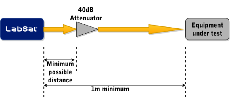
Basic wired test setup
Test Creation and Configuration
In order to calibrate the test fixture, two variables must be found; the required LabSat attenuation and the SNR levels expected from the equipment under test. Both of these values can be found by using the following procedure:
- Use SatGen Software to create a static scenario with 8 GPS satellites at 51 dB.
- Place a known good example of the end product in the test fixture and play the scenario from the LabSat.
- Monitor the signal-to-noise ratios (SNRs) reported by the unit with the LabSat set to 0 dB of attenuation.
- Wait for the equipment to track all 8 space vehicles (SVs), they should have the same SNR ±1 dB and the reported SNRs should be stable. If this does not happen, decrease the external attenuation by 20 dB and try again.
- Slowly increase the LabSat internal attenuation until any of the following events happen: The equipment under test loses lock, the differences in SNR between satellites starts to increase, or the SNRs start to vary by more than ±1 dB over time. These are all indications that the equipment is having trouble tracking the signals and so the minimum reliable signal strength has been found.
- Once this point is located, decrease the LabSat internal attenuation by 10 dB. If the internal attenuation is under 10 dB, decrease the external attenuation by 15 dB and return to step 3.
- This reduced attenuation setting will be the signal level used for testing.
Note: The SNR levels reported by the user equipment will determine the test pass criteria.
By following this process, the signal levels reaching the equipment under test will be within a range where variation in receiver sensitivity will have the maximum possible impact on reported signal levels.
Test process
To test a device, place it in the test fixture and replay the same LabSat scenario.
Wait until the device has acquired a stable GPS position fix, if this takes over 2 minutes then the device may well be faulty.
Record the reported SNR values and compare them to the values received from a known good unit. There will be unit to unit variation in the reported signal levels, how great this variation is will depend on both the consistency of the test environment and natural product variation, however as a rough guide, any unit reporting SNRs 3 dB or greater below the known good unit should be considered suspect.
Test maintenance
It is good practice to verify the test set up at regular intervals and if any changes are made to it, no matter how minor. This is done by testing a known good unit and ensuring that it reports the expected results.
Many RF connectors are only rated for a few hundred connect/disconnect cycles. Depending on the planned volumes, it may be prudent to design the fixture such that the connection to the equipment under test can easily be replaced should it become worn.
Radiated testing for devices with internal antennas
Testing devices with internal antennas is also possible but adds some additional challenges.
In order to be meaningful, production testing must use very weak signals, which introduces the risk of confusion between the test signals and the live GPS signals. This combined with very strict legal restrictions on broadcasting within the GPS frequency band mean that any radiated testing must be carried out within a shielded enclosure.
The small separations between the transmitter and receiver imposed by the use of a chamber in turn means that very small differences in device position or environment can have a significant impact on measured signal strength.
In order to produce a reliable and consistent test, it is critical that the device under test be consistently located, that the separation between the antennas is maximised (this reduces the sensitivity to placement variation) and that any connected cables be as short as possible and routed consistently between tests so as to minimise the risk of cable placement influencing the test results. If possible, devices should operate without any cables connected.
It is also critical that the RF chamber be closed and sealed for the duration of the test. If user interaction is required, for example to press buttons or read results, then these actions must be performed before or after the test.
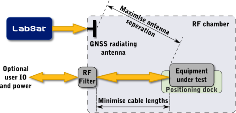
Reradiated test setup
Other than the extra care required in ensuring the test environment is consistent, the overall test structure is the same as detailed above for a wired configuration. Due to the losses involved in re-radiating the GNSS signals, the need for additional attenuation may well be eliminated, however this will be highly dependent upon the final physical test configuration and the sensitivity of the equipment being tested. In some situations, an external amplifier may be required to boost the signal levels. If this is the case, then a low noise amplifier with a pass band that includes 1575 MHz should be used such as the Mini Circuits ZFL-1000LN+.
Testing multiple devices at once
It is possible to test multiple devices at once with a single LabSat, however this does introduce two additional complexities.
Firstly, either the tests must be synchronised such that they all start at the same time as the LabSat scenario, or if each test station runs independently, the scenario must be set to loop continuously. If using a looping scenario, care must be taken to ensure that a device is not being tested when the scenario restarts. If this does happen, the device under test must be cold started and the test started again.
The second complexity is ensuring that the signal levels are consistent between all the devices being tested. While not technically required, failing to do this would result in different pass/fail criteria for each test station which would in turn greatly increase the risk of operator errors during testing.
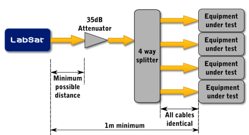
Multi-device test setup for conducted testing
The simplest way to achieve equal signal strengths is to ensure that all cables after the RF splitter are of equal length and identical construction. While this may still result in some minor variations in signal strength, they should be small enough to not have any significant impact on the overall test reliability. If for some reason this is not possible, then it may be necessary to increase the power going in to the RF splitter by reducing the attenuator connected directly to the LabSat output by ~5 dB and then add additional small attenuators to each cable after the splitter until all test stations give the same results.
The RF splitter and additional connectors and cabling required in a multi-station test environment will result in a reduced signal strength at each test station, e.g. an ideal 4-way splitter will add 6 dB of loss, the extra cables and connections involved will normally add 1 or 2 dB more giving a total signal reduction of ~8 dB. In order to compensate for this, the signal levels from the LabSat should be increased by approximately the same amount, i.e. for a conducted test setup, the 40 dB attenuator is reduced to somewhere between 30 and 35 dB for a 4-way split. For radiated testing in which there is often no external attenuator to reduce, this may require additional signal amplification.