LabSat 3 CAN-Bus Logging
Overview of CAN Bus
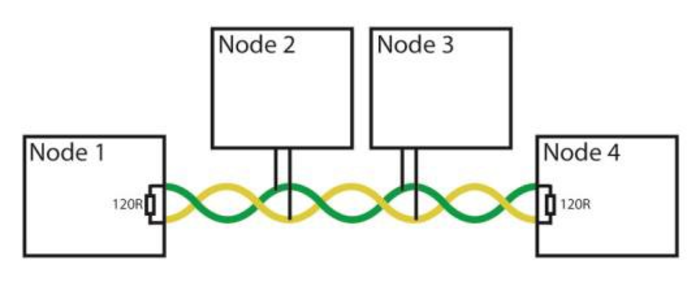
CAN Bus (Controller Area Network) is a network data-link that is often found in industrial and automotive environments. It allows a number of electronic control units to share data using a single pair of twisted wires. To form a working CAN Bus, there must be at least two control units (Nodes) and 120 ohm terminating resistors at each end of the bus. Data is transmitted in frames that consist of an identifier and up to 8 data bytes. When a node on the CAN bus transmits a data frame, other nodes respond with an acknowledge pulse at the end of the frame to show that it has been received correctly. If the transmitting node does not receive an acknowledge pulse, it will re-transmit the frame a number of times before flagging an error and giving up.
.png?revision=1)
Labsat 3
In addition to GNSS signals from an antenna, Labsat 3 is capable of listening to, and recording data from, two separate CAN networks. Dual channel CAN Bus data recording with Labsat 3 can be achieved in two ways. Depending on the mode selected, the CAN signal will be either digitized and re-created on a raw bit level or decoded and recorded in a time-stamped text file. The CAN mode of operation is selected under the menu option ‘CAN’ in the SETUP section.
DIGITIZE mode
The ‘Digitize’ mode records CAN data by listening to the bus and sampling the rising and falling edges of the raw signal. Timing codes are inserted into the recorded GPS data so that when the file is replayed, LabSat re-creates the digitized CAN signal exactly as it appeared during recording. This mode can therefore be used to capture data along with bus-errors or data-collisions and is synchronised to the RF signal to within 62 nanoseconds. One advantage of this mode is that there is no-need to configure CAN baud rate. During replay, the CAN data can be viewed with a CAN Bus analyser tool such as Vehicle-SPY or CANAlyzer.
One point to note with the digitize method is that because the CAN data is replayed exactly as recorded, there will be no arbitration with other systems during replay. Therefore, if the CAN data is replayed into a system which is transmitting its own CAN data, LabSat will ‘speak’ over the top of the other CAN data causing corruption of some data frames.
LOG FILE Mode
Selecting the ‘LOG FILE’ mode of CAN recording enables data to be recorded in an easy to read text log file as shown below.
1.png?revision=1)
The log file contains a short header detailing the LabSat serial number, time, date and CAN Bus baud settings. Each line of CAN data recorded contains the following space-delimited information:-
- CAN Channel that the data was received on. 1 or 2
- Timestamp to 1 ms resolution
- Identifier. ‘x’ suffix is shown for extended CAN IDs.
- Data length code DLC. This shows the number of data bytes within the CAN frame.
- Data section. Up to 8 bytes of data as indicated by the DLC.
The end of the log file contains a summary of the number of CAN messages received on each channel during recording.
The log file is recorded in the same folder as the RF data and has a .TXT file extension.
During recording, the CAN controller listens to the CAN bus and stores incoming data. LabSat will transmit acknowledge pulses on the bus in response to correctly received data unless the ‘Silent Record’ option is ticked. The ability to transmit acknowledge pulses in LOG FILE mode means that it is possible to record data directly from inertial sensors or other devices with a CAN bus output.
During replay of data recorded in the LOG FILE mode, LabSat scans through the log file, sending the CAN data at the time intervals indicated by the time-stamp. Because CAN data is transmitted using an active CAN Bus controller, LabSat will arbitrate by listening to the current bus state and only transmitting the data between other messages that may be sent from other nodes.
Filtering of Selected CAN Frames in LOG FILE mode
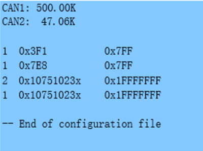
Filtering of selected CAN frames in the LOG FILE mode can be achieved by creating a file called CANFILTER.TXT in the root directory of the current SD/HDD. An example of the CANFILTER.TXT file is shown below.
.png?revision=1)
The first two statements automatically configure the CAN Bus baud rates:-
- CAN1: 500.00K – This means 500 kbit/s
- CAN2: 47.06K – This means 47.06 kbit/s
The next set of lines, configure the required Identifiers for each channel. The format is:-
<CHANNEL><IDENTIFIER><MASK> , for example 1 0x3F1 0x7FF means that channel 1 will allow recording of identifier 0x3F1. The mask value of 0x7FF is a bit-wise mask that is used by the CAN controller to allow a single identifier of a range of identifiers to be recorded. If the mask value was set to 0x7F0, then identifiers from 0x3F0 to 0x3FF would be recorded, not just 0x3F1. Up to 16 identifiers can be defined for each CAN channel.
Summary of Two CAN Modes
| DIGITIZE | LOG FILE | |
|---|---|---|
| During Record | No need to configure CAN baud rate. No CAN acknowledge transmitted by LabSat. Data is embedded in the RF data so no extra files are generated. |
Baud rates for each channel must be configured. Acknowledge pulse transmitted by LabSat unless configured otherwise. Generates separate text file for the CAN data. |
| During Playback | CAN data generated exactly as recorded irrespective of other CAN traffic. No acknowledge required by LabSat from other nodes. |
CAN data replayed as close as possible to recorded timestamp but will vary subject to other bus traffic. At least one other active node is required on the bus to ensure acknowledge is received by LabSat. |
| Used for.. | Capturing CAN data with exact timing and then viewing the data with a CAN analyser during replay. Replay into a CAN bus that has no other transmitting nodes. |
Capturing CAN data with millisecond accuracy. Data logged to separate text file for viewing in Notepad or Excel. Replay includes active arbitration so may be used to test in situations where other nodes are also transmitting CAN data. |
| Note | CAN Data embedded in RF recording so there is no separate CAN file to view. |
CAN Data stored in separate text file so uses more SD card/HDD drive bandwidth. If recording full CAN traffic and two constellations, will require recording to external USB HDD/SSD drive to avoid buffer overflow. |
During Record
During record and depending on the CAN mode, LabSat 3 may or may not transmit acknowledge pulses to show correct reception of data. Digitize mode will never send any acknowledge, while Log File mode will always acknowledge other nodes unless its ‘Silent’ option is selected. In most cases, it is not an issue whether or not LabSat transmits acknowledge pulses as there will generally be other nodes on the bus that will send them anyway. However, if recording from a single CAN bus device such as an inertial sensor (IMU), then Log File mode must be used and the ‘Silent’ option must be un- ticked so that the LabSat correctly acknowledges receipt of the IMU data. In this case, it is also important that the bus is terminated with 120 ohm resistors. Although the CAN Bus specification requires 120 Ohm resistors at each end of the bus, in practise, for short cable lengths, a single 120 ohm resistor at one end is sufficient. The RLACS202 adapter has on-board 120 ohm resistors on each CAN channel which can be jumper selected.
During Replay
For both CAN modes, it is important to make sure that the CAN Bus is correctly terminated with a 120 ohm, resistor at each end of the bus.
When using Log File mode, Labsat will require an acknowledge pulse from at least one other CAN node to ensure that each CAN frame has been correctly sent.
Example Connection 1
Recording data from two separate networks that already have 120 ohm termination.
.png?revision=1)
Example Connection 2
Recording data from single CAN node on channel 2. Requires termination resistor and ensure that LabSat CAN channel 2 has ‘Silent’ disabled so that it sends acknowledge pulse back to Node 1.
.png?revision=1)
