TSR - Traffic Sign Recognition Testing (Multi Static Point)

The VBOX can track up to 100 static points and report precise positions and angles to these targets which is used when validating Traffic Sign Recognition systems.
Enabling Multi Static Point Mode
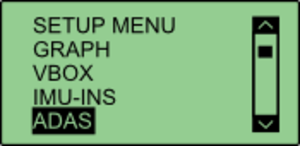
1. Using 'VBOX Manager' enter the 'SETUP' menu.
.png?revision=1)
2. Then select 'ADAS'.
.png?revision=1)
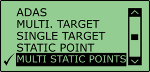
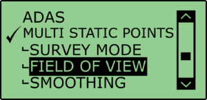
3. Select 'MULTI STATIC POINTS'.
.png?revision=1)
4. Once selected, a ‘tick’ icon will be displayed next to the 'MULTI STATIC POINTS' menu and it would have expanded to include:
- Survey Mode
- Field of View
- Smoothing
.png?revision=1)
The VBOX is now set to 'MULTI STATIC POINTS' mode.
Setting the ‘Field of View’The Field of View is a circular arc that defines when a feature should be referenced, represented as the orange area in the diagram below. If a static point lies outside of this area, it will be ignored until it enters the field of view.
|
.png?revision=1)
Defining the Field of View using VBOX Manager1. Under the 'MULTI STATIC POINT' menu, enter the 'FIELD OF VIEW' menu. |
2. Enter the 'OFFSET' menu. This menu allows the user to translate the antenna position to another position on the vehicle (usually the sensor position).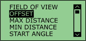.png?revision=1) |
3. The offset point will be the start of the field of view. This is done by entering either a 'LNG RANGE' and 'LAT RANGE' offset, with forwards and right directions being positive..png?revision=1) |
|
4. Enter the 'MAX DISTANCE' menu. In this menu it is possible to define the distance, in metres, from the offset point that the field of view will end. .png?revision=1) |
5. Once the distance has been set, press the 'APPLY' button..png?revision=1) |
6. Enter the 'MIN DISTANCE' menu. Similar to the 'MAX DISTANCE' menu, this allows the user to define the distance from the offset point that the field of view will start.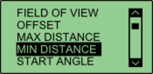.png?revision=1) |
7. Once the distance has been set, press the 'APPLY' button..png?revision=1) |
8. Enter the 'START ANGLE' menu. This allows the user to define the angle from the centreline at which the field of view will start. Anything to the left of the centre line will be negative, anything to the right hand side will be positive..png?revision=1) |
9. Once the angle has been set, press the 'APPLY' button..png?revision=1) |
10. Enter the 'END ANGLE' menu. This allows the user to define the angle from the centreline at which the field of view will end. Anything to the left of the centre line will be negative, anything to the right hand side will be positive..png?revision=1) |
| 11. Once the angle has been set, press the 'APPLY' button. |
Setting Static Points1. Under the 'MULTI STATIC POINTS' menu, enter the 'SURVEY MODE' menu. |
2. Select the 'EDIT POINTS' menu..png?revision=1) |
| 3. To define the first point of a feature, move the antenna to the required position and press 'POINT 1'. If successfully saved, VBOX Manager will display the 'OK' message. .png?revision=1) To define the second point of a feature, move the antenna to the required position and press 'POINT 2'. If successfully saved, VBOX Manager will display the 'OK' message. Note: This step can be skipped if the user requires the feature to only have one point. |
|
4. Once one/both points have been surveyed, select 'NEXT'. .png?revision=1) |
5. VBOX Manager will then display a 'FEATURE 1 SAVED' message..png?revision=1) |
| Repeat this process as required. |
The saved features can be cleared at any time using the 'CLEAR POINTS' option under the 'SURVEY MODE' menu..png?revision=1) |
.png?revision=1)
Saving Static PointsOnce the static points have been surveyed, it is possible to save all surveyed static points. |
1. Under the 'SURVEY MODE' menu, select 'SAVE POINTS'. This allows the user to either create a new save file, or replace an existing file..png?revision=1) |
2. To replace a file, simply select the file name you wish to replace, in this case, the file called 'EXAMPLE'..png?revision=1) |
3. To create a new file, select '{CREATE NEW}'. This will bring up an alpha numeric scroll wheel where the user can enter the desired file name..png?revision=1) |
| 4. Once saved, VBOX Manager will display a 'SAVE SUCCESSFUL' message. |
Loading Static PointsIf a previously saved file is present on the compact flash card, it is possible to load those points. |
1. Under the 'SURVEY MODE' menu, select 'LOAD POINTS'. This will bring up a list of all previously saved files that are present on the compact flash card..png?revision=1) |
2. Selecting a file name will load that file into the VBOX..png?revision=1) |
SmoothingIf the box is set into twin antenna mode, the smoothing menu will not be present as the calculations will run off of the True heading provided by the twin antenna lock. It is recommended that if user intends to set multiple points on the car, they enable the dual antenna. There are two configurable variables linked to heading smoothing; ‘Smoothing Distance’ and ‘Speed Threshold’. Due to the nature of the vehicle separation measurement and calculation process many channels are derived using the heading of the vehicle which can inherently be noisy. To overcome this heading can be smoothed with a dynamic smoothing routine. |
Smoothing Distance
|
|
Above: Shows the improvement on vehicle heading from using smoothing distance |


Setting A Smoothing Distance |
| 1. Select ‘SMOOTHING' from the 'MULTI STATIC POINTS' menu. |
2. Select ‘SMOOTHING DIST' and enter the smoothing option for the Subject Vehicle, from the options between 0.00 m and 2.00 m..png?revision=1) |
| 3. For typical Vehicle Separation applications we recommend a smoothing distance of 1 m. |
Speed ThresholdDue to the nature of how heading is calculated, even when Smoothing is applied at very low speeds and when the vehicle is stationary the heading channel can become very noisy and unusable, this in turn results in many of the Vehicle Separation channels becoming noisy at low speed and unusable when stationary. This is solved by fixing the heading below a configurable Speed Threshold. |
1. To set the speed threshold repeat step 1 above, then select 'SPD THRESHOLD' and enter the speed threshold option for the Subject Vehicle..png?revision=1) |
| 2. We recommend a Speed Threshold of 5 km/h. |