J2263 Coastdown Testing with VBOX 3i
The SAE J2263 Coastdown Test is a test plugin for the VBOX Test Suite software.
The test itself gives you the ability to complete a coastdown test to the SAE J2263 specification. By using wind speed and direction inputs, the software will automatically apply the required equations to produce a road load force.
This guide will detail the requirements for the hardware and software setup of the test equipment from Racelogic, taking the mounting requirements outlined by the J2263 specification into consideration.
Equipment
Required Hardware
- VBOX 3i data logger
- VBOX Manager
- VBOX MFD Touch (Optional)
- Anemometer
(We recommend the RM Young 05103 Anemometer) - Windows PC
Required Software
Hardware Configuration
|
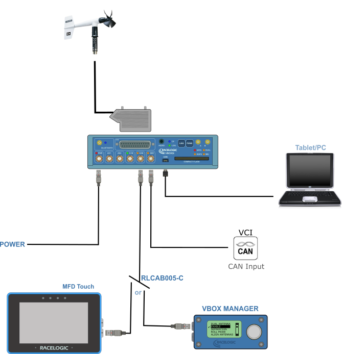
You can use any VBOX 3i unit for the J2263 testing. However, based on the VBOX 3i hardware version, there will be some differences in the software configuration. These differences are shown in the software setup further down on this page. You can find more information about the VBOX 3i compatibility here. Before you can perform a J2263 Coastdown test, you must connect and configure the required hardware. The following is a connection diagram of the basic equipment you will need for this test. |
|
 |
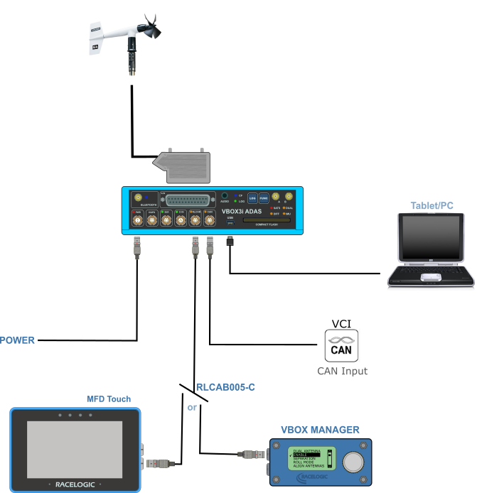 |
| Hardware connection diagram with VBOX 3i | Hardware connection diagram with VBOX 3i ADAS |
| Note: When you are performing a coastdown test, you do not need to run Kalman Filtering. If you are using an IMU, we recommend that you use the supplied RLCAB120 to connect it to the CAN port on the VBOX 3i unit or the RLCAN port on a VBOX 3i ADAS unit. |
Connecting the Anemometer
|
You can connect the anemometer to the VBOX 3i unit by using the D-sub 25-pin adaptor in the VBOX 3i kit. You can then connect the D-sub 25-pin adaptor to the 25-pin connection on the front of the VBOX 3i unit. You will need to wire the anemometer cable into the D-sub 25-pin adaptor using the following wiring diagram: |
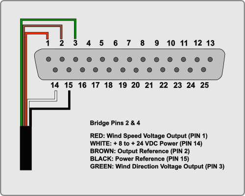 |
Mounting the Anemometer
|
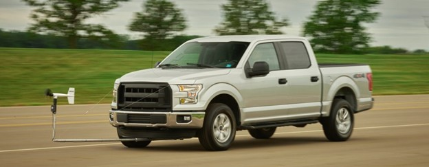
When you have connected your hardware, you need to mount the anemometer on the vehicle. Traditionally, the anemometer is mounted out in front of the vehicle. It is your responsibility to physically mount the antenna as Racelogic does not provide a mounting solution for the anemometer. The anemometer should be mounted facing in-line with the body of the vehicle. The RM Young anemometer has a 360-degree physical rotation. In practice, however, there is a dead spot between 0 and 5 degrees. Based on the SAE spec, if an anemometer has a dead spot in its measurement, you should mount it with the 0-position of the anemometer 90 or 180 degrees offset to the body line of the vehicle to avoid the dead spot during calibration. |
|
Example of a vehicle with an anemometer mounted. |
Software Configuration
|
When you have connected and mounted the hardware on the vehicle, you can begin your software setup of the VBOX 3i unit.
|
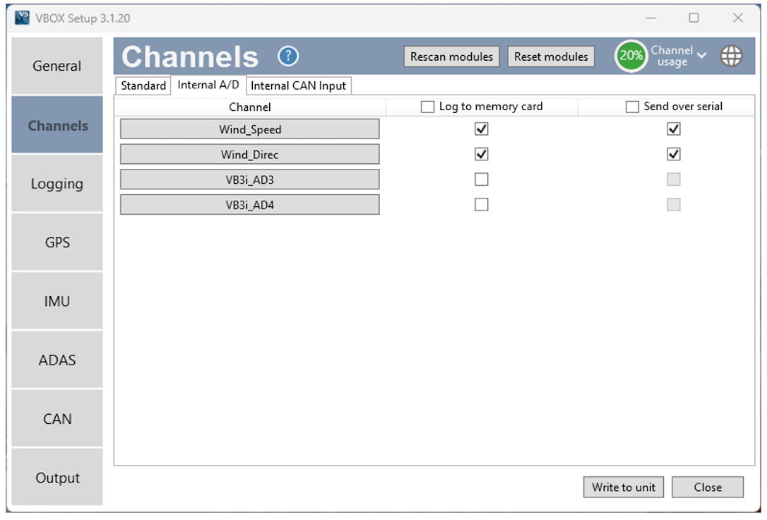
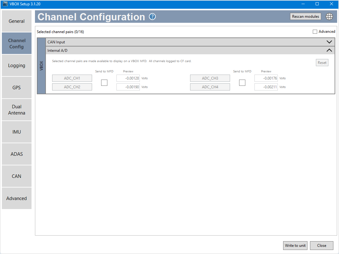
| VBOX 3i Firmware v2.8 and Earlier | VBOX 3i Firmware v3.0 and Later |
 |
 |
|
|
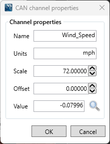
Wind Speed
|
 |
|
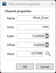
Wind Direction
|
 |
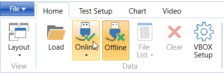
You are now ready to begin the coastdown testing. Data AnalysisYou can either run the coastdown test in the online mode in VBOX Test Suite and see the data in real-time or you can do the analysis offline in VBOX Test Suite Online Mode
Offline ModeAn alternative to using online mode is to log all the required data to the compact flash card and do your data analysis in VBOX Test Suite in offline mode. |