02 - DAC01 Software setup
Hardware connection
Configuration of the DAC01 is performed using VBOX Setup software. Using the supplied RLCAB001 cable, connect the serial port on the DAC01 to the computers 9 way D serial port – this can be done via a serial > USB converter if required.
Software connection
Use the drop down list to select the COM port the DAC01 is connected to. Once the correct COM port is selected the DAC01 setup screen will automatically be displayed.
.png?revision=1)
Software
General
.png?revision=1)
- Connection – Selected com port, refresh and disconnect buttons.
- Load/Save – Load/Save settings from/into a Racelogic settings file (.RSF). This allows setups to be kept for future use.
- Language – Select an operating language.
- Write to unit – After making changes to setup, the write to unit button must be selected to upload settings.
- Unit Information – Serial number and installed firmware version of connected unit.
Channels
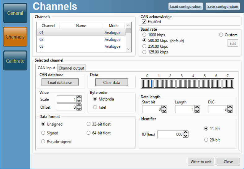
In this section, the eleven configurable channels can be set up to convert CAN data to either analogue, level or frequency. Note some of the channels have a fixed output mode, as listed below.
.png?revision=1)
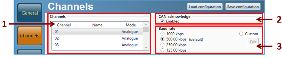
- Channel list – Shows the channel name and states if the output is configured to analogue, level or frequency. Select a channel here to configure or view its input and output settings.
- CAN acknowledge – Set whether CAN acknowledge is enabled or disabled. CAN acknowledge is needed when connecting the ADC01 to a CAN bus system which is not currently active.
- Baud rate – Set the baud rate which the DAC01 will read CAN data from.
CAN input tab
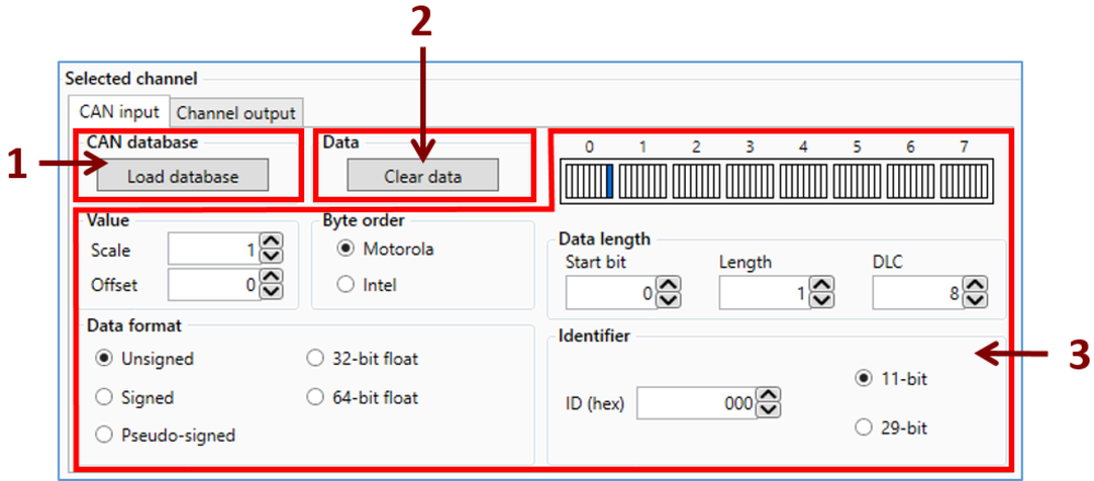
- Load CAN database – Here a CAN database file (.DBC .REF or .VCI) can be selected to load a CAN input parameter into the currently selected channel.
- Clear data – Selecting this will clear any CAN input data.
- Channel info – This section will show the CAN input details of the selected channel, or allow new details to be manually entered. Note that if a REF file is loaded, this section will be mostly blank as REF CAN data is encypted. The only accessible settings in this case would be scale and offset, see images below.
.png?revision=1)
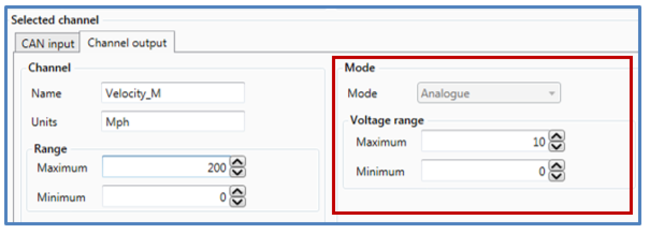
Channel output tab
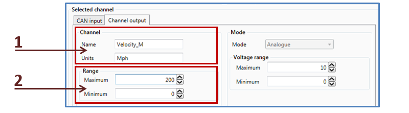
- Channel details – Enter or change selected channel name and units.
- Range – Expected input value minimum and maximum for selected channel.
Analogue mode
Set the minimum and maximum voltage range to be output by the DAC01 module. This corresponds directly with the expected input range as set on the left hand side of this screen.
.png?revision=1)
Level mode
Here, high and low threshold values can be set, providing three different output states.
Each state can have a 0v or 12v signal associated with it.
For example, this setup is such that once the satellite count is over 10, 12v will be output. As soon as the count drops under 10, the output will drop to 0v.
.png?revision=1)
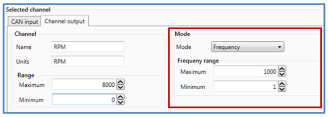
Frequency mode
Set the minimum and maximum frequency range to be output by the DAC01 module. This corresponds directly with the expected input range as set on the left hand side of this screen.
.png?revision=1)